1
\$\begingroup\$

I'm band new to electricity and electronics and am confused by something I saw with a recent video that explains how to connect a battery, LED and resistor together. In that article (see link for further details if you're interested), its a 9V battery, a 3V LED rated at 20mA and a resistor that are being used.

  • Is it OK/safe to connect the LED to a voltage source providing more voltage than it is rated for? What potential side effects are there? I think the answer here is yes, because it seems perfectly fine to hook a 3V LED up to a 9V battery.
  • Is it OK/safe to connect the LED to a voltage source providing less voltage than it is rated for? What potential side effects are there? Pretend I only had, say, a 1V battery.
\$\endgroup\$
2
  • \$\begingroup\$ LED's are cheap, I suggest you get a few, play around and see what happens. (Do you have a cheap DMM?) (oh don't play with AC line voltages until you know more.) \$\endgroup\$ Commented Sep 8, 2017 at 16:24
  • \$\begingroup\$ LED's behave just like Zener diodes with adding a series R voltage drop to limit current. Obviously 9V wastes power, so consider a lower battery voltage like 3.6V LiPo cell with a smaller R or direct on a 3V Lithium battery for a couple days use. \$\endgroup\$
    – D.A.S.
    Commented Sep 8, 2017 at 16:31

4 Answers 4

2
\$\begingroup\$

As far as over voltage, read here: How can voltage burn out an LED? Under voltage, it will not light or be very dim.

\$\endgroup\$
3
  • \$\begingroup\$ Hmmm, thanks @LsD (+1) - so it sounds like you're saying that the resistor is added into the circuit to reduce the voltage from 9V -> 3V? If that's what you're saying, I thought resistors' job is to limit how much current (not voltage) is being drawn, no? Thanks again! \$\endgroup\$
    – smeeb
    Commented Sep 8, 2017 at 16:21
  • 2
    \$\begingroup\$ That's not what I'm saying. Voltage and Current are intimately related. They are not separate. Did you read all of the information in that link? The answer for your question is not as simple as you think it is. \$\endgroup\$
    – LsD
    Commented Sep 8, 2017 at 16:23
  • \$\begingroup\$ @smeeb think of it like this, if the LED presented as a short circuit, the current that would flow through it would be exactly Vin/R, and that is the worst case current that could possibly flow through that LED, hence a current limit. \$\endgroup\$
    – vicatcu
    Commented Sep 8, 2017 at 16:53
1
\$\begingroup\$

Applying more voltage than the LED is rated for will cause it to overheat and burn out / catch fire if you really overdo it.

Of course that is assuming the battery can source that much current. You may just find the battery voltage drops off...

Applying less voltage will make it dimmer.

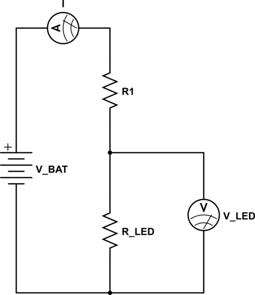
ADDITION: To address your voltage/current confusion look at the simple circuit below..

schematic

simulate this circuit – Schematic created using CircuitLab

R1 is your drop or ballast resistor, R_Led is the effective resistance of the LED when it is on. We do not normally think of LEDS as presenting a resistance, but in fact they do have a complex effective resistance. For the purpose of this description it makes things a little clearer.

Can you see that the current through the LED will simply be

\$I = V_{BAT}/(R1 + R_{LED})\$

And that the voltage across the LED is

\$V = V_{BAT} - (I * R1)\$

OK so maybe the math confuses you..

Can you visualise what happens when you INCREASE R1...

When you do, you increase the total resistance of the circuit so the current must be less. At the same time, since R1 got larger compared to R_LED, the voltage V MUST drop.

As such, the ballast resister sets both the voltage AND the current through an LED for a particular supply voltage within the tolerances of the LED's forward voltage.

\$\endgroup\$
4
  • \$\begingroup\$ Hmmm, thanks @Trevor (+1) - so it sounds like you're saying that the resistor is added into the circuit to reduce the voltage from 9V -> 3V? If that's what you're saying, I thought resistors' job is to limit how much current (not voltage) is being drawn, no? Thanks again! \$\endgroup\$
    – smeeb
    Commented Sep 8, 2017 at 16:21
  • \$\begingroup\$ @smeeb it does both. You cant really do one without the other. By dropping some voltage through the resistor you limit the current. or you limit the current with a resistor which drops the voltage to the LED... they are the same thing in different words. \$\endgroup\$
    – Trevor_G
    Commented Sep 8, 2017 at 16:26
  • 1
    \$\begingroup\$ @smeeb think of it like this, if the LED presented as a short circuit, the current that would flow through it would be exactly Vin/R, and that is the worst case current that could possibly flow through that LED, hence a current limit. \$\endgroup\$
    – vicatcu
    Commented Sep 8, 2017 at 16:52
  • \$\begingroup\$ @smeeb see my updated answer \$\endgroup\$
    – Trevor_G
    Commented Sep 8, 2017 at 17:34
0
\$\begingroup\$

One does not regulate an LED by regulating the voltage applied to it: One regulates the current. The reason is, an LED's IV Curve is very steep near its normal operating point. Small fluctuations in voltage cause large changes in current. If you try to regulate the voltage, you risk exceeding the maximum current rating, and burning out the LED.

The cheapest way to regulate the current* is what they showed in the video: put the LED in series with a ballast resistor (a.k.a., "current limiting resistor"). That makes the current/voltage relationship much more manageable.

The most efficient way is to use a constant current power supply. (often called an "LED driver" when designed especially for LED lighting applications.)


* Actually, there's a cheaper way: In keychain flashlights that use tiny button cells or coin cells for power, they often just connect the LED directly to the battery. In those designs, the battery itself acts as the ballast resistor. All batteries have internal resistance, and smaller the battery, the more resistance it tends to have.

\$\endgroup\$
0
\$\begingroup\$

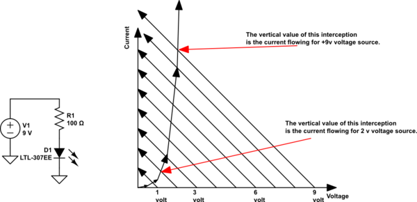
Lets examine the behavior of 2 circuit components connected in series: a resistor & an LED, that series circuit connected across a voltage source. We keep the same resistor value, and increase the voltage from 1 volt to 9 volts, in 1 volt steps.

schematic

simulate this circuit – Schematic created using CircuitLab

\$\endgroup\$

Your Answer

By clicking “Post Your Answer”, you agree to our terms of service and acknowledge you have read our privacy policy.

Not the answer you're looking for? Browse other questions tagged or ask your own question.