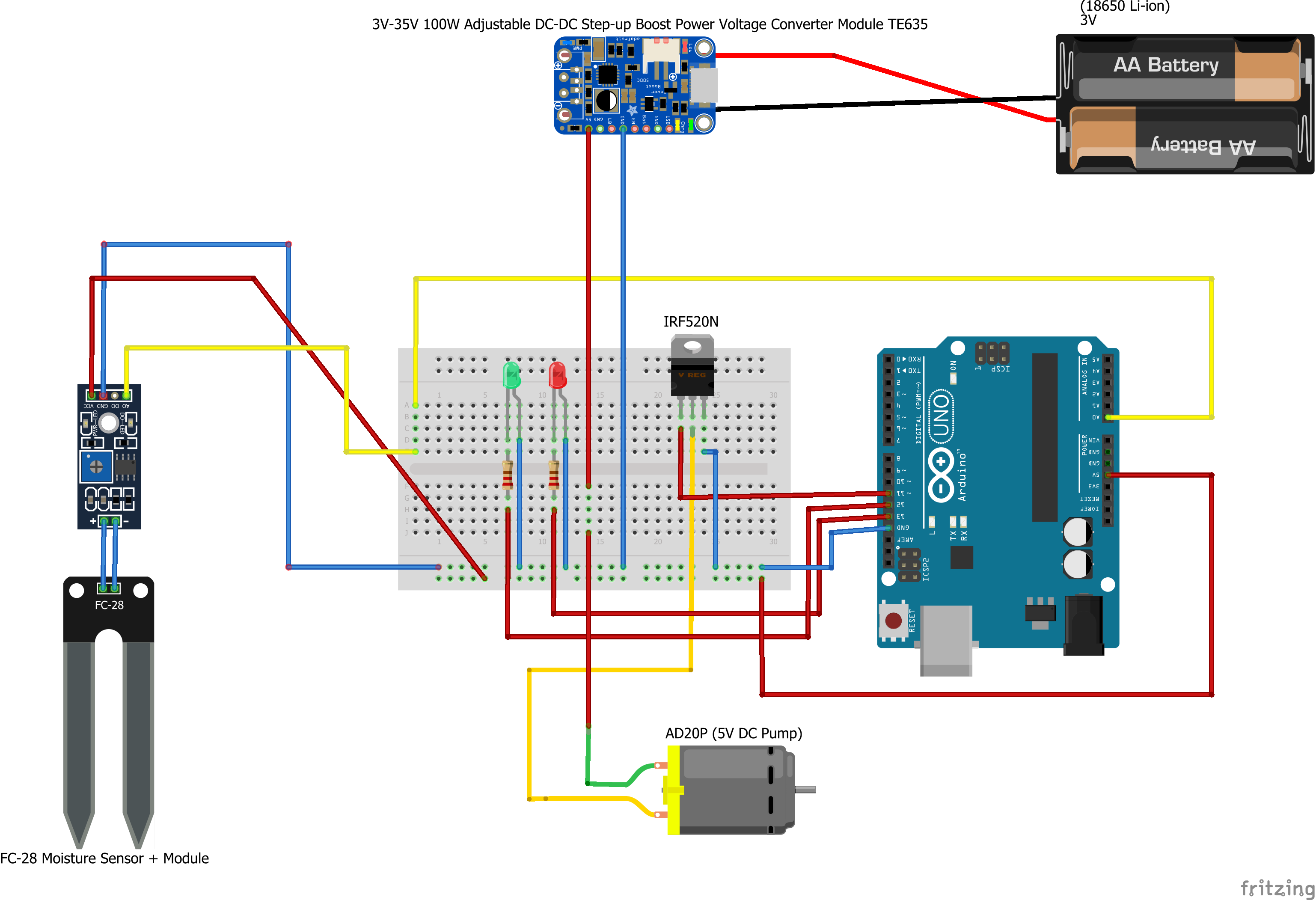
Each time the pump is activated, the DC-DC converter (bough from here) shows that the voltage drops to 0V, although the pump still works and I'm not sure if this is normal or not.
Since you say that the pump still works (and is therefore still receiving power from that Ebay boost converter module) then the display on that module must be misleading you. The output from the boost converter cannot be both zero (as shown by its display) and non-zero (as shown by the pump operating) at the same time!
Unfortunately it is impossible to diagnose the reason for this behaviour with certainty as neither you, nor the readers here, have the schematic for that module, the firmware for its display MCU (see below) and the ability to make all the necessary measurements.
This situation of "why does the module from Ebay / AliExpress behave like that?" is the price paid for using those cheap modules. :-( As I have mentioned on other answers, since buyers can't realistically get the necessary support from an Ebay / AliExpress vendor, then buyers have to either reverse-engineer the module themselves and provide their own support - or else accept that they will never know why strange things happen. :-(
The question is... why does it drop to 0V when the pump is turned on?
The output doesn't drop to 0 V, because if it did then the pump could not operate - but as you have pointed out, the pump does operate even when the display on the boost converter module shows 0 V.
Using an oscilloscope (to be able to see the peaks) or a multimeter (which can only show slow changes) would allow you to see more about what the output voltage is actually doing, to avoid being misled by the display on the boost converter module.
According to the images in that Ebay listing, the 7-segment display on that boost converter module is driven by an STM8S MCU (similar to many stand-alone 7-segment voltage displays also available on Ebay). We don't know whether that could get confused or behave incorrectly, with certain types of loads... Perhaps the current peak when starting that pump is a problem for that boost converter module?
There are two components missing from the diagram supplied, which might have an impact on the behaviour you describe:
- Missing flyback diode across the motor (add one, to prevent damage to the MOSFET - although it might already be too late to avoid damage to the MOSFET which is already being used).
- Missing bulk smoothing capacitor (e.g. hundreds of uF) close to the motor. That will help to reduce the peak current load on the boost converter.
Also:
The IRF520N MOSFET (Infineon datasheet, Vishay datasheet - I don't know which brand you have) is not the most suitable for this job. It is not a "logic-level" MOSFET and at a 5V Vgs, it is not fully saturated (i.e. it is operating in the linear region) and will only be able to pass a limited current (and will heat up more while it's doing that). The datasheet shows optimal switching at around 10V Vgs, which you cannot achieve from the output of an Arduino.
I would also suggest adding a pull-down resistor between the MOSFET Gate and Gnd, so that it isn't floating before your Arduino sets that pin as an output. A small Gate drive resistor might also help, especially when driving MOSFETs with large Gate capacitances directly from an MCU.
These topics have been handled before in other questions and so can be researched there.

