1
\$\begingroup\$

I have several single coil latching relays, (low rep points so not hyperlinking), mouser.com/ds/2/212/KEM_R7002_EC2_EE2-540906.pdf (EC2-5SNU).

I am trying to control them by an MCU; connected directly they work fine, but I am iffy about keeping it this way so I'm trying to power them through a darlington pair array: ti.com/lit/ds/symlink/ulq2004a.pdf (ULN2003).

Using the non-latching type, these work fine through the ULN2003, but attempting to interface the code below with the latching type isn't going so well and i can't figure out why:

int right = 12;
int left = 10;

void setup() {                
  pinMode(right, OUTPUT);     
  pinMode(left, OUTPUT);    
}

void loop() {
  digitalWrite(right, HIGH);  //reset
  digitalWrite(left, LOW);  
  delay(2000);              
  digitalWrite(right, LOW); //set
  digitalWrite(left, HIGH);   
  delay(2000);       
}

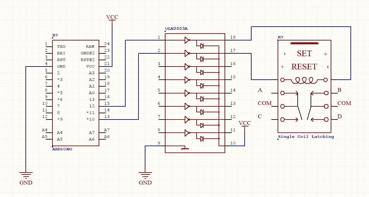
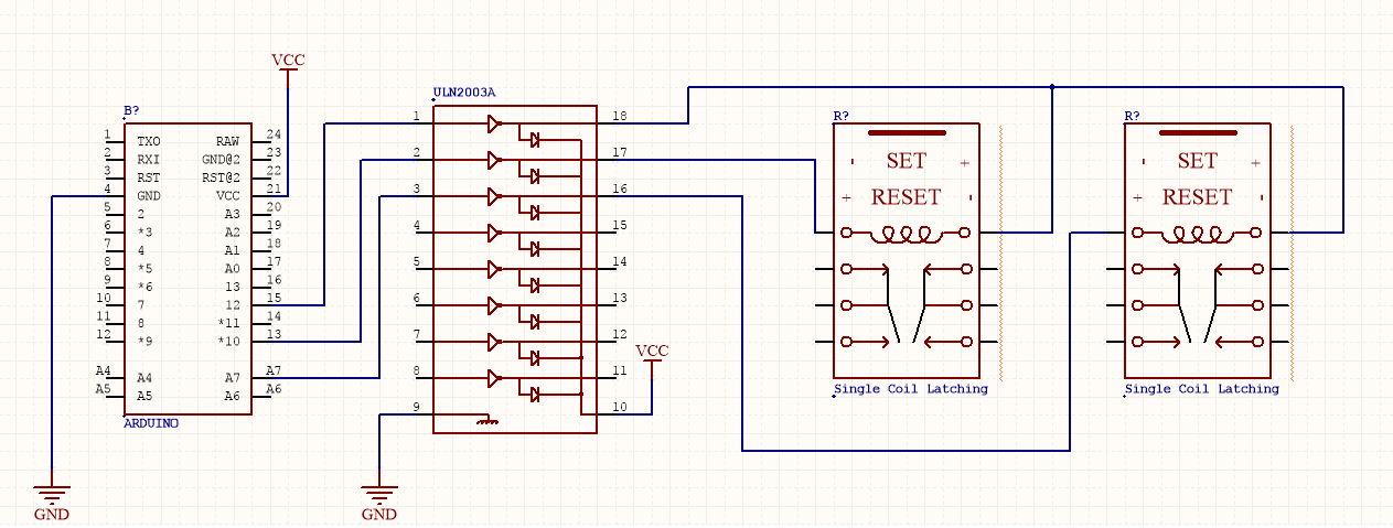
I have four connected with a common pin, but to simplify i've tried and failed to have the code above work on a single relay, as shown below:

enter image description here

enter image description here

Measuring the voltages out of the MCU show the correct levels, keeping in mind the ULN2003 acts an inverter, so i've set the boolean logic accordingly.

The voltages at the output of the ULN seem to stick at 0.6V, I've tried a bunch of permutations, including having one pin (on the common pin setup) connected directly to the MCU.

Does anyone have any ideas?

\$\endgroup\$

1 Answer 1

3
\$\begingroup\$

As I think you understand, for this model of the relay there is only one coil and set and reset are carried out by polarity reversal. This is indicated on the schematic symbol.

enter image description here

Figure 1. Coil polarity for set and reset operation.

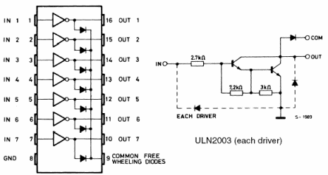
The problem is with the ULN2003.

enter image description here

Figure 2. The ULN2003 inverter and a detail of one output stage.

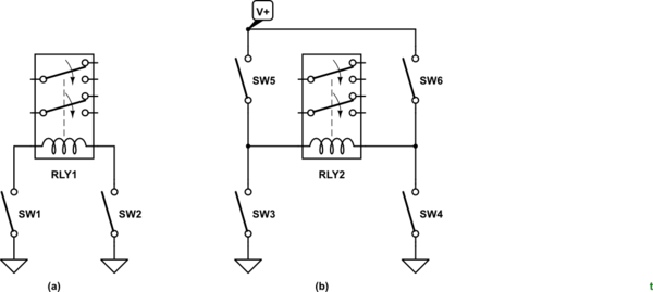
Notice that this is an open-collector transistor output stage. It can only pull low (sink) and cannot source (supply) current.

schematic

simulate this circuit – Schematic created using CircuitLab

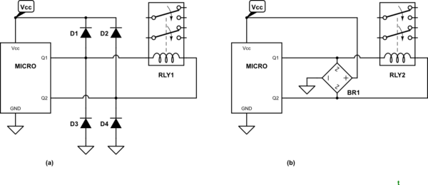
Figure 3. (a) What you created (in top schematic). (b) What you need - H-bridge.

You need a little redesign. A simple H-bridge would do the trick.

I don't know which coil voltage you are using but it may be possible to drive the relay coils directly from the micro-controller. Calculate the current required from the coil specifications on page 8 of the datasheet. Then compare this to the maximum source and sink currents of the micro-controller. Watch the chip total current too. You might be constrained to energising one coil at a time.


schematic

simulate this circuit

Figure 3. Snubbing options. Option (b) integrates the four diodes into a bridge rectifier saving some PCB space and soldering.

\$\endgroup\$
8
  • \$\begingroup\$ Calculated value is 25mA at 5V, so I can go back to driving the relays direct from the MCU. I do latch/pulse on relay at the time so it should be safe, but can i ask: do i need any kind of spike protection or other component for it to be safe? \$\endgroup\$ Commented Sep 27, 2017 at 13:15
  • \$\begingroup\$ I knew i needed some diodes somewhere - thanks for the help! Edit: correct me if i'm wrong, but most MCUs should have D3 and D4 connected internally, may have been D1 or D2, i need to double check. It's something i figured out from Dave via EEVBlog. \$\endgroup\$ Commented Sep 27, 2017 at 17:23
  • \$\begingroup\$ Yes, each GPIO will have a pair of diodes similar to the external pair on Fig. 3a. In many cases these are inherent in the design of the output transistors rather than an additional "component" on the chip. They are very small, though, and their primary benefit is electrostatic discharge protection. We cheat and use them sometimes as part of our circuits but for a relatively high current (> few mA) it would be bad practice. They can also give unexpected problems. See an article I wrote - High-side driver fail for an example. \$\endgroup\$
    – Transistor
    Commented Sep 27, 2017 at 17:43
  • \$\begingroup\$ I know it's a bit overkill, but would this bridge rectifier suffice? eicsemi.com/DataSheet/KBL400.PDF Trying to find something with the smallest footprint, maybe some schottky or small signal diodes might suffice. Edit: maybe this is best, since it's smaller package and relatively cheap. Still would consider some 1N4148's. farnell.com/datasheets/1441680.pdf \$\endgroup\$ Commented Sep 28, 2017 at 15:04
  • \$\begingroup\$ Two things: current rating and turn-on speed. (1) At the instant of switching the diodes will take over supplying whatever current was flowing so they have to be rated adequately for that. (Not a problem in your case.) (2) The need to turn-on quickly otherwise they'll make very poor clamps. Your first choice is a power diode so it would probably not be a good choice for reason 2. I did a quick scan of the datasheets linked but couldn't see any reference to switch-on speed. \$\endgroup\$
    – Transistor
    Commented Sep 28, 2017 at 16:45

Your Answer

By clicking “Post Your Answer”, you agree to our terms of service and acknowledge you have read our privacy policy.

Not the answer you're looking for? Browse other questions tagged or ask your own question.