2
\$\begingroup\$

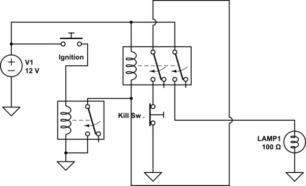
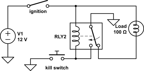
I'm working on a little circuit to place on a vehicle, the expected functionality is to add a kill switch that when pushed it will stop voltage to my load, in the schematic i represent it with a bulb. For it to work again the vehicle should have to ignition off and on again. the following schematic works ok with the following exception. if I do not press the kill switch my load will also stop having voltage once my ignition is off(this is only desired when the switch is pressed, the ignition on is the event where it resets back to on).

schematic

simulate this circuit – Schematic created using CircuitLab

\$\endgroup\$
6
  • \$\begingroup\$ @jsotola what would that change? I can change the type of switch with ease \$\endgroup\$ Commented Jun 11, 2018 at 16:45
  • \$\begingroup\$ Are you saying that the circuit should normally stay on when ignition switch is off? \$\endgroup\$
    – Transistor
    Commented Jun 11, 2018 at 16:45
  • \$\begingroup\$ Why do you care what state the switch is in when it's unpowered? \$\endgroup\$ Commented Jun 11, 2018 at 16:46
  • \$\begingroup\$ @Transistor, yes unless the kill switch was pressed, if the kill switch was pressed it should stay off until the next ignition \$\endgroup\$ Commented Jun 11, 2018 at 16:47
  • \$\begingroup\$ @cristobol because my load is some ki d of security device \$\endgroup\$ Commented Jun 11, 2018 at 16:48

2 Answers 2

2
\$\begingroup\$

I don't think you can do quite what you specified with only one relay.

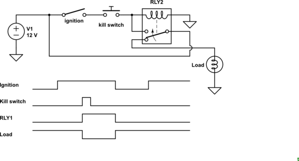
If you are prepared to modify your requirements so that the circuit is reset when the ignition is turned off (rather than off and back on again) then the solution is simple.
schematic

simulate this circuit – Schematic created using CircuitLab

Figure 1. The modified circuit with all switching in positive lines.
schematic

simulate this circuit

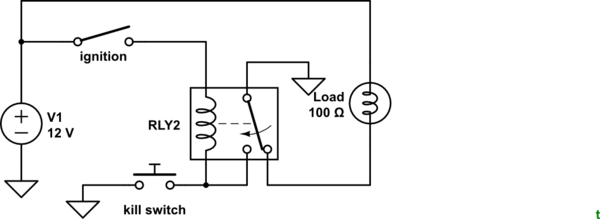
Figure 2. By moving the load positive to bypass the ignition switch the OP's circuit timing and operation will match that of Figure 1.
schematic

simulate this circuit

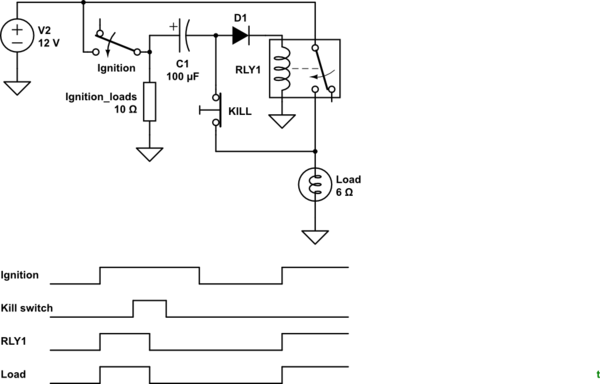
Figure 3. A capacitive "kick" circuit and latch.

How it works:

  • When the ignition is turned on both sides of C1 rise to +12 V. C1 is sized to provide enough energy to energise the relay.
  • The relay contact will then maintain power to the coil and switch on the load.
  • If KILL is pressed the relay will be de-energised. Note that since C1 has been charged via the latch circuit that KILL will have to be held for long enough for the relay to drop out. The delay is shown in the timing diagram. This 'feature' may be enough to make this an unsuitable solution.
  • D1 prevents the coil energising on a negative going pulse when the ignition is turned off.

For a coil resistance of R a rough idea of the time delay is give by \$ \tau = RC \$. This will need to be at least as long as the pick-time response of the relay.
\$\endgroup\$
7
  • \$\begingroup\$ Nice, a proper S-R flip-flop would need two memory devices and your circuit is the next best thing if the inability to shut the load off with ignition off can be tolerated. \$\endgroup\$
    – KalleMP
    Commented Jun 11, 2018 at 17:54
  • \$\begingroup\$ @Transistor Thanks, your answer is very elaborated. The delay might even be good for my application so that it is not pressed by accident. where the ignition load is that is basically a resistor? or what is that? \$\endgroup\$ Commented Jun 11, 2018 at 21:55
  • \$\begingroup\$ It's all the stuff that turns on with the ignition - dashboard lights, radio, the heater, rear window demisters that you forgot to turn off when you last stopped the car and, of course, the ignition system itself. I drew it in because it's important to remember that it's there. When ignition is turned off the ignition load will quickly pull the capacitor to ground. Without D1 a negative pulse would be seen by the relay and this might energise it since most are not DC polarity sensitive. \$\endgroup\$
    – Transistor
    Commented Jun 11, 2018 at 22:01
  • \$\begingroup\$ I am trying it out on a simulator and the relay wont engage, the coil's resistance in the simulator is 20 ohms inductance is 200mH what should the caps value be to turn it on? \$\endgroup\$ Commented Jun 11, 2018 at 22:11
  • \$\begingroup\$ I'll turn the question back on you: what turn-on time did you use and what \$ \tau \$ (time constant) did you calculate and what C value did that suggest? \$\endgroup\$
    – Transistor
    Commented Jun 11, 2018 at 22:13
1
\$\begingroup\$

Well, there should be two sets of contacts, one for the real load and the other for the latching control loop. The latch circuit loop should have the normally closed "kill switch" inline so it can open the circuit. Also, there should be a pulse relay to establish the loop. So you should have something like this:

schematic

simulate this circuit – Schematic created using CircuitLab

Also: some ignition switches have a set of switch contacts to ground. So the ignition pulse relay might not be needed because the ignition switch could temporary give the latching relay a ground in that situation.

\$\endgroup\$
4
  • \$\begingroup\$ Your relay can never pick up. I've got a different problem in my solution. \$\endgroup\$
    – Transistor
    Commented Jun 11, 2018 at 17:34
  • \$\begingroup\$ oh yea!, doh! it needs to be an interlock circuit, thanks @Transistor \$\endgroup\$
    – drtechno
    Commented Jun 11, 2018 at 17:51
  • \$\begingroup\$ Don't skimp on the correct capitalisation! Your answer looks semi-literate when you do and takes away from its credibility. \$\endgroup\$
    – Transistor
    Commented Jun 11, 2018 at 19:33
  • \$\begingroup\$ My knowledge level is 9 out of 10, but my writing skills is a 3. I will try to improve this @Transistor. \$\endgroup\$
    – drtechno
    Commented Jun 13, 2018 at 15:13

Your Answer

By clicking “Post Your Answer”, you agree to our terms of service and acknowledge you have read our privacy policy.

Not the answer you're looking for? Browse other questions tagged or ask your own question.