5
\$\begingroup\$

I'm trying to understand how a car alternator efficiently charges the battery.

I don't understand why a power-factor controller isn't needed to effectively use the alternator. Current would only flow out of the windings when their voltage is a diode drop above the load (battery), so an alternator that put out 15V peak would produce current only a very short portion of each cycle. This would seem to result in a very low utilization of the windings and very high peak currents.

Or does the alternator act more like a current source than a voltage source?

\$\endgroup\$
2
  • 2
    \$\begingroup\$ Not sure "power-factor controller" is the term you really mean here. \$\endgroup\$
    – Trevor_G
    Commented Oct 31, 2017 at 3:43
  • 4
    \$\begingroup\$ google rectified 3-phase waveform ... here is an example ... it is almost DC ... upload.wikimedia.org/wikipedia/commons/4/4c/… ... it is not a technical explanation, but it shows how the dips in the voltage are filled in by the multiple phases \$\endgroup\$
    – jsotola
    Commented Oct 31, 2017 at 4:22

4 Answers 4

7
\$\begingroup\$

A car alternator is indeed operated as a current source, but regulated to a maximum voltage limit.
Providing the alternator is turning at sufficient speed (rpm), if you shorted the field to 12 V and had the output open circuit you would produce about 70-80 VDC. When connected to a battery (and charging) the current is only limited by the design (max field current) and the field is turned off/reduced (it's actually operated as PWM in most designs) if the voltage goes above the set limit.

If you slow the alternator rpm to a point where it cannot produce sufficient voltage output (even with maximum field current), then obviously it cannot charge the battery. However once it has sufficient rpm to produce more than the voltage required, it will have minimal ripple on the output since it has a 3 phase full wave rectifier. Each rectifier pair conducts for 120 degrees total so the ripple is very low.

enter image description here

Something like this may help you.

A vehicle alternator is only about 50-55% efficient at best, and when you take other losses into account it approaches only about 25% overall efficiency. See here for a great explanation.

If you are planning on using the alternator for any project use, you can consider changing to Schottky diodes, FET based rectifiers and/or raising the output voltage.
There is lots of material on 42 V DC systems, and you can get a quite normal car alternator to produce this voltage with new MCU based electronic controls. This increases the efficiency and output power capability considerably.
This paper by Tang et al is a good point to start, and this paper is well worth reading on more granular details.

\$\endgroup\$
0
\$\begingroup\$

How your typical cars electrical generation system works is a good deal more complex than most people understand it to be.

The three phase alternator does indeed produce three sinusoidal voltages each 120 degrees apart and the three phase rectifier taps off the peaks of those waves when the voltage is greater than the regulated voltage.
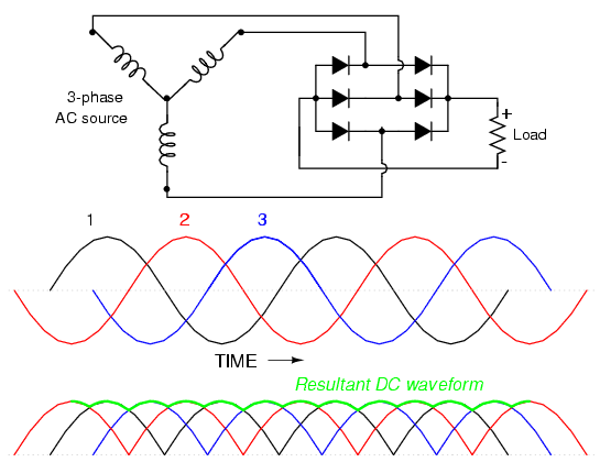
enter image description here

That may appear, as you have questioned, that we are not using the full power available from the alternator. However it is not that simple. You can not consider the alternator as a stand-alone power source like a battery or power supply that has a fixed input source.

An alternator converts mechanical energy that it draws from your engine and converts it into electrical power. How much energy it needs to take, and how much it loads down your engine, is dictated by how much electrical power you take out of the coils.

Current is indeed only drawn from each phase of the alternator during the high point in it's voltage cycle. However, that also means, during the rest of the cycle, the coil pulls no power from the engine.

This means the power transfer from the engine to your electrical load is also rectified through the rectifier with no significant losses other than those inherent in the voltage drops across the diodes, and the efficiency of the alternator itself.

Further, alternators are not permanent magnet dynamos. The magnetic field the coils turn in, is created by the field coil, an electromagnet if you will. The current that is fed through that coil is what determines how much voltage is produced by the alternator.

When you turn the key in the ignition, you are no doubt aware that there are two spots. The first one connects the battery to the electrical system and may be labelled "accessories". The second spot is labelled "ignition" and this one connects the alternator field coils, and whatever engine controllers your more modern car may have. The ignition light on your dashboard, traditionally, is in series with the field coil. It will be lit at this point because the coil is receiving max current and will go out when the engine is started and the alternator begins producing power and the field current is reduced.

The field coil current is controlled to keep the output voltage a few volts above the battery voltage over the entire operating speed range of the engine and the electrical load applied to the system.

As the engine speeds up, or you turn off the window defogger, the field current reduces to keep the voltage within the required range. Further, it also means the power taken from the engine is constant for any given electrical load.

The power taken from the engine also causes the engine control system to compensate. When idling, if the electrical load is high, it will tend to drag the engine slower. The idle or engine controller will advance the idle speed to create more power to compensate. When cruising along, its the drivers foot that does the compensation.

As for whether it is a current or voltage source, it is an oversimplification to think of it that way. It is actually a voltage regulated power convertor.

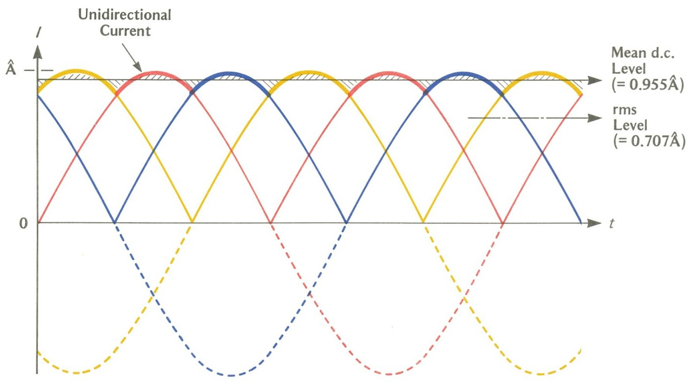
\$\endgroup\$
4
  • \$\begingroup\$ The alternator loads the motor with a constant load. Each diode pair results in close to 120 deg conduction for a total of 360 deg. There is ripple, but it is low. The fact that only one phase provides power at any given time is totally irrelevant ...it supplies a constant (almost) current into the battery and a constant load on the engine. \$\endgroup\$ Commented Oct 31, 2017 at 15:48
  • \$\begingroup\$ @JackCreasey isn't that what I just said... \$\endgroup\$
    – Trevor_G
    Commented Oct 31, 2017 at 15:52
  • \$\begingroup\$ Not as I read it. \$\endgroup\$ Commented Oct 31, 2017 at 16:03
  • \$\begingroup\$ @JackCreasey it's all in there, but may need emphasizing differently. I'm always open to edit suggestions. Feedback is always welcome. \$\endgroup\$
    – Trevor_G
    Commented Oct 31, 2017 at 16:04
0
\$\begingroup\$

But with the continual desire to improve mileage, I would think that increased efficiency in a car alternator would be a good way to get that last .2 mpg. Also, in wind-power installations, where the output is rectified to DC, (before running through a 60Hz inverter) very important?

Something must be wrong in my thinking, because if I'm right, every alternator that has rectified DC output should have a Power Factor Controller as part of the system. But they don't. Is is just because people haven't cared that they waste power? Or that the cost is too high?

\$\endgroup\$
-1
\$\begingroup\$

I totally understand how 3 phase devices work. I design KW off-line power supplies. But every design I do includes a Power Factor Controller to deal with the problem of only drawing current from the line when the rectifiers are forward-biased. The power line has a very low source impedance. A power factor controller consists of a "boost" converter that boosts the incoming rectified AC to 370V. The boost converter uses an inductor + FET + Schottky and a controller to boost even low voltages to the 370V level, so current is drawn over the entire cycle - even near zero-crossing. The controller changes the pulsewidth to the FET gate during the cycle in order to produce a current waveform that exactly matches the voltage waveform. So a PWM controller looks like a resistive load to the line.

When I design for 3-phase, I use 3 complete power factor controllers and tie their 370V outputs together. That way, all 3 phases "think" they are connected to resistors. That keeps the power company (and the regulatory agencies

When I look at a car alternator, I see the same problem: If the alternator truly puts out 15V peak, then current is flowing only when the waveform is above (12.6V + .7V) which isn't much of the cycle. This would be very inefficient, and would result in very high peak currents.

The only explanation I can think of is if the alternator is operated as a current source, and the open-circuit voltage is much higher than 15V. Then the coils would be utilized to a much higher degree, since the voltage waveform would exceed 15V early in the cycle. When the battery got charged OR disconnected, the regulator would then reduce the field current to reduce or stop the current to prevent the voltage from going any higher.

I always thought of a generator/alternator as a "hard" voltage source (low source resistance). Is that incorrect?

My neighbor has a small John Deere lawn tractor. It has a permanent-magnet alternator. I'm very curious as to how the regulator on that works. I would think it would need a full switching power supply in order to deal with the battery. And I see ads for permanent magnet alternators on the net. They are sold for home wind-power installations. Wouldn't you need to add a Power Factor Controller on the output of the alternator in order to get full utilization of the coils and to regulate the output voltage?

Or am I all wrong?

\$\endgroup\$
1
  • \$\begingroup\$ "this would be very inefficient" true, but think about what is in the car : an alternator that uses 10 to 15 bhp and an engine that may produce between 120 to 300bhp : why would the manufacturer care about efficiency??? Why do you think people know that turning the A/C off gives more power for acceleration... \$\endgroup\$
    – Solar Mike
    Commented Nov 1, 2017 at 13:35

Your Answer

By clicking “Post Your Answer”, you agree to our terms of service and acknowledge you have read our privacy policy.

Not the answer you're looking for? Browse other questions tagged or ask your own question.