0
\$\begingroup\$

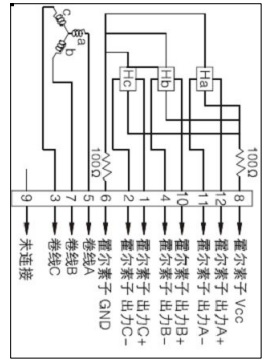
I am trying to control a 3 phase brushless dc motor with integrated hall-effect sensors. I understand how to do this with your typical open-collector hall effects, however according to the manufacturer these are "line-driver" hall effect sensors. I do not understand how to read them.

Instead of just having 1 output for each halleffect this motor appears to have 2. I have hooked 12v to Vcc and Ground to ground and measured the output of both the + and - output of the halleffects. There seems to be 3 possible outputs at each output ~6.86, ~5.8, ~ 5. I have to be missing something right??

I have attached the very limited information the manufacturer has given mepinout
\$\endgroup\$

1 Answer 1

0
\$\begingroup\$

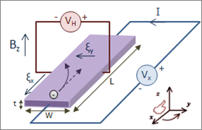
A "raw" Hall effect sensor will give an output voltage proportional to the current and orthagonal magnetic field.

enter image description here

Figure 1. The principle of the Hall effect. Source: Wikipedia Hall effect.

  • In your case it seems as though you have two output terminals per sensor. These would correspond to \$ V_H+ \$ and \$ V_H- \$ in Figure 1.
  • Since the Hall effect produces quite low voltages it seems reasonable to assume that some amplification of the signal takes place in the chip.
  • Since the chip has single rail supply it also makes sense that the voltage would vary around mid-supply. This is 5.8 V in your case.
  • It also seems plausible that there are three possible states for the sensor:
    • North pole at sensor.
    • Neither or balanced / cancelling / opposing poles at sensor.
    • South pole at sensor.
  • These three options would explain your three output voltages. More than likely you should find that when A+ is high that A- is low and vice versa. You should also find that when A+ is neutral that A- is too.

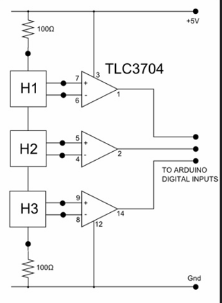
To "decode" these signals you will need three analog comparators.

enter image description here

Figure 2. The only similar circuit found on a web search shows the three sensors in series rather than parallel. This is an efficient approach where possible as the series current reduces overall current consumption. The TLC3704 contains four comparitors. Image source: Flickr.

\$\endgroup\$
2
  • \$\begingroup\$ Ok, what you are saying makes perfect sense. However I have a concern with simply using a comparator to decode the signal. When A+ and A- are both neutral I can still have 35mv of differential voltage between them.... Is there a way to account for this? \$\endgroup\$ Commented Nov 3, 2017 at 22:06
  • \$\begingroup\$ Hysteresis on the comparitor is what you need. Since you've got about 1 V low to high I'd be looking for about 0.25 V hysteresis. You'll have to figure out how to do that with the comparator you choose. Generally you add a little positive feedback. Plenty on the web on the subject. \$\endgroup\$
    – Transistor
    Commented Nov 3, 2017 at 22:17

Your Answer

By clicking “Post Your Answer”, you agree to our terms of service and acknowledge you have read our privacy policy.

Not the answer you're looking for? Browse other questions tagged or ask your own question.