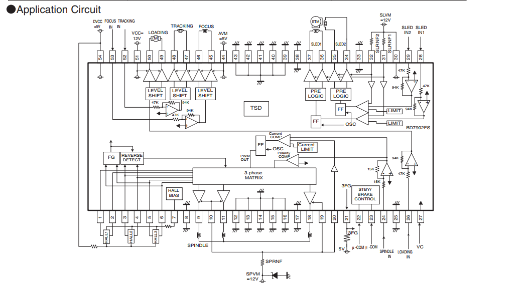
I have a CD-ROM that I would like to use the stepper motor from. I specifically would like to use the existing driver for it. The circuit diagram for this driver, the BD7907FS, is below. I understand how the stepper motor works, but do not know how to use this chip to control it. I am used to a 'step' and 'dir' pin, where as it appears, this IC has a "SLED IN1" and "SLED IN2" pin (pin 28 and 29), which I assume is how you control the sled's stepper motor. I could also use help determining the input voltage for said pins.
-
\$\begingroup\$ This chip drives all five motors in the CD. You only intend on using the microstepping sled driver? \$\endgroup\$– glen_geekCommented Nov 24, 2017 at 1:23
-
\$\begingroup\$ Yes that is my intent. \$\endgroup\$– Cameron KCommented Nov 24, 2017 at 1:46
1 Answer
My notes are for measurements made on the similar BD7902 chip.
SLED_in1 has measured average voltage of 1.412V
SLED_in2 has measured average voltage of 1.412V
This average voltage also appears on pin 27, called "VC" and must be above 0.7 volts to awaken the sled motor driver.
The two sled control inputs are driven with analog quadrature sinusoidal signals something like this:

One full cycle of these two inputs gives one "step". Current sense resistors feeding pins 31 and 32 are also required. These are in the 0.5 to 1.0 ohm ballpark. +12V and +5V supplies are required as well.
Driver logic control pins 22, 23 seem to control subsections of this chip. For the BD7902, pin 23 must be pulled to logic high for the sled motor, spindle motor, focus motor, tracking motor to be active. Pin 22 seems to be don't-care as far as the sled is concerned (it controls door loading motor).
Unlike the "step" and "direction" controller that you're familiar with, this one does microstepping to keep the sled from jerking from step to step, although the controller does have some non-linear deadzone region around the VC voltage.
If your interest is sled motion only, and you don't need fine control of laser position, a coarse, digital stepper-like drive to
SLED_in1 & SLED_in2 should be possible so that the sled motor can be driven in both directions:

These digital signals might be generated by a microcontroller or counter chip, but should be attenuated and a 1.4V DC offset added...these will be accepted as analog signals by the BD7907.
-
\$\begingroup\$ Powering the drive through molex, I find that the VC and Sled IN1 and Sled IN2 are all at 1.2V. How would I go about sending the signals you mentioned to step the motor? Could any of the other chips on the board of the CD-ROM allow me to control this? \$\endgroup\$ Commented Nov 24, 2017 at 17:56
-
\$\begingroup\$ @CameronK I don't think so...This is a complex servo system where the sled motor and tracking motor work in concert to position the laser. Are you using the laser, or are you only interested in moving the sled? I have edited this answer with an idea for coarse stepper drive of the sled. \$\endgroup\$ Commented Nov 24, 2017 at 18:22
-
\$\begingroup\$ Yes thank you! this is much more of what I intended to do and that definitely helps out! Thanks for the great response. \$\endgroup\$ Commented Nov 25, 2017 at 3:28

