0
\$\begingroup\$

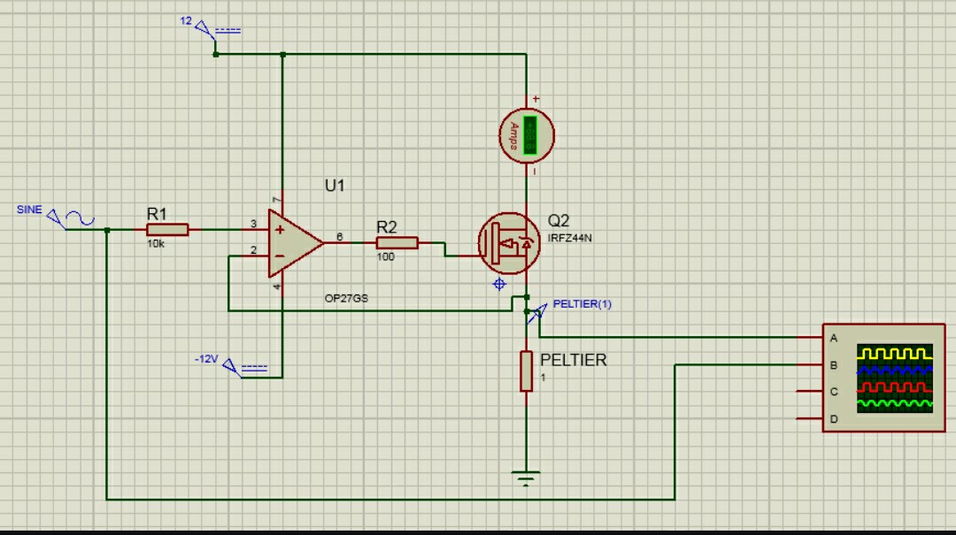
enter image description here

Hi People... I`m working on a Project to create a Colling controled box using peltier elements..

The circuit above works as a voltage follower, dropping DC voltage on the peltier. Allthough its working, when i reach 5Vdc at the input The peltier cell(2 in parallel) only drives 5amps. Even when i increase the dc input tô 6 or 8 volts, mosfet is still delivering 5amps at Max(remember its 2 cell in parallel) . Why is that? I wish i could work at full power these cells...

Here it is a test I was able tô reach 8 degress celsius
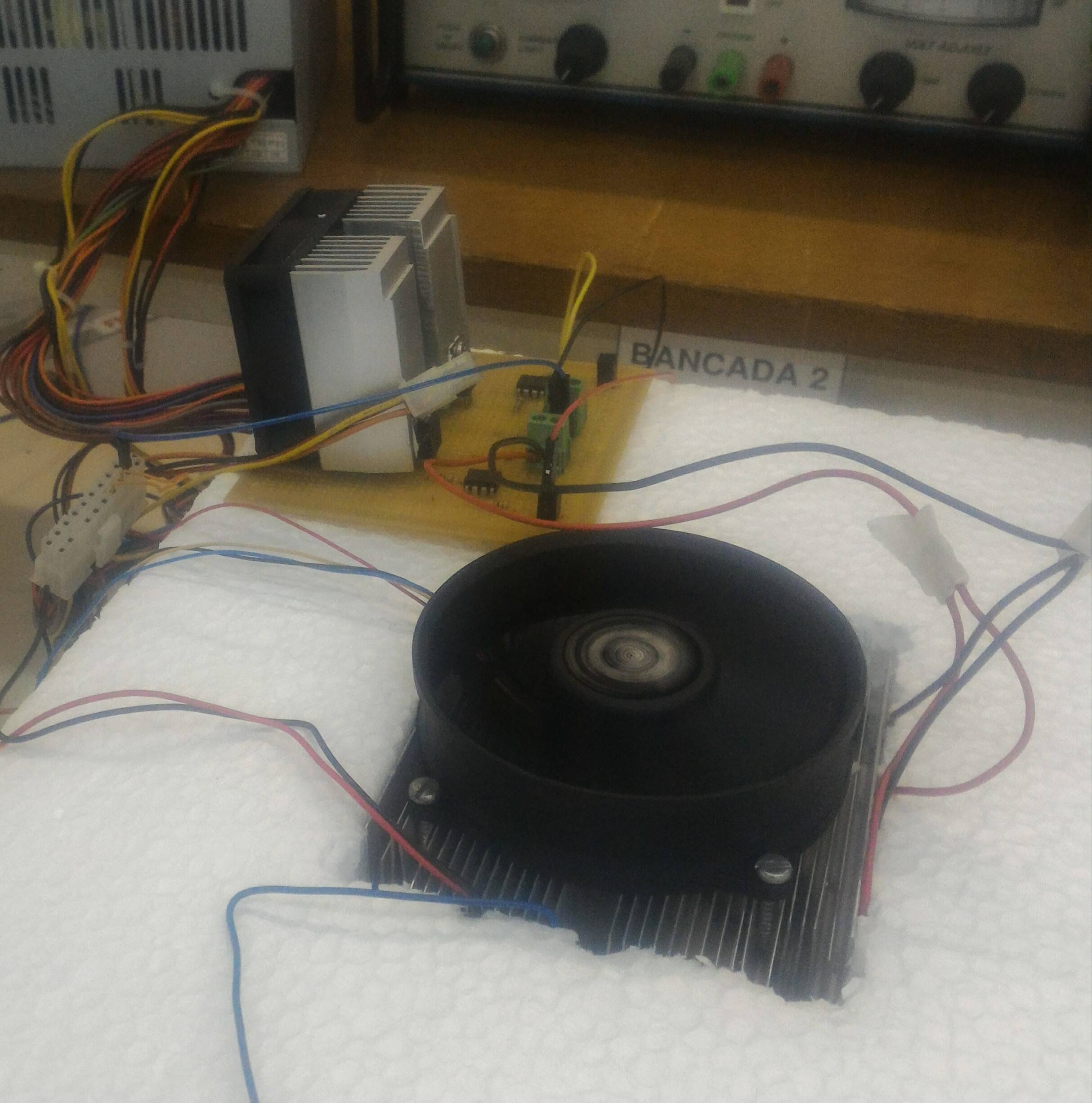
enter image description here

\$\endgroup\$
5
  • \$\begingroup\$ Well, what kind of cells are those and how they should be driven? Look up the datasheet, most peltiers I know are meant to be driven with 12V or above \$\endgroup\$
    – PlasmaHH
    Commented Nov 30, 2017 at 16:12
  • \$\begingroup\$ What is the resistance of the peltier? \$\endgroup\$
    – Trevor_G
    Commented Nov 30, 2017 at 16:18
  • \$\begingroup\$ its an htc 40-10-15.4 ----- 10amp - 15.4v \$\endgroup\$ Commented Nov 30, 2017 at 16:36
  • \$\begingroup\$ in parallel its 1,8Ohms \$\endgroup\$ Commented Nov 30, 2017 at 16:39
  • 1
    \$\begingroup\$ OH look.... Styrofoam \$\endgroup\$
    – Trevor_G
    Commented Nov 30, 2017 at 20:39

1 Answer 1

1
\$\begingroup\$

OK so your max output on the op-amp is about 9V and the MOSFET needs 4V to turn on.... 9-4 = 5V. That sounds about right to me for what you are seeing.

Ditch the MOSFET and use a regular NPN transistor or Darlington. Since you are running it in linear mode anyway, the MOSFET does not buy you much other than low gate current.

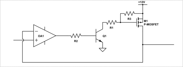
Or better, change your circuit to use a P channel MOSFET like so.

schematic

simulate this circuit – Schematic created using CircuitLab

\$\endgroup\$

Your Answer

By clicking “Post Your Answer”, you agree to our terms of service and acknowledge you have read our privacy policy.

Not the answer you're looking for? Browse other questions tagged or ask your own question.