0
\$\begingroup\$

I did some soldering and breadboarding and implemented the precision rectifier circuit as presented in enter image description here
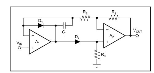
which was taken from an Burr-Brown Application note sboa068.

R1, R2 and R3 are all 10k, the Opamp chosen was an AD8602 and the Diodes chosen were BAT54 (due to the lack of better-suited diodes at the moment)

The opamps are powered by a split power supply of +/-2.5V and I feed a sinusoidal input signal to the circuit while having a scope on the output.

I use a input signal amplitude of 1Vpp and vary the frequency from about 10kHz to 200kHz. Unfortunately, I see a large variation in the output amplitude of the rectified signal.

When feeding 30kHz, i have an output amplitude of about 400mV instead of 500mV, then when increasing the frequency to about 50kHz I get the correct amplitude of 500mV Peak, when further increasing the frequency to 200kHz, I get an amplitude of about 710mV. I measured the resistirs R1 and R2, which have 10.016k and 10.011k respectively, so that cannot explain such a large variation in "gain".

According to a LTSpice simulation with the correct spice models, the circuit works rather fine down to about 80mVpp, where amplitude starts to fall off.

Any suggestions?

\$\endgroup\$
8
  • \$\begingroup\$ 1. The used amplifier is not from sboa068 app note list of opamps. 2. breadboard is not a tight PCB with small paths and guards to prevent stray capacitances. \$\endgroup\$ Commented Dec 18, 2017 at 16:21
  • 1
    \$\begingroup\$ Is the gain flat from 100 Hz to 10 kHz? \$\endgroup\$
    – AnalogKid
    Commented Dec 18, 2017 at 16:54
  • \$\begingroup\$ How are you measuring the input signal? \$\endgroup\$ Commented Dec 18, 2017 at 16:55
  • \$\begingroup\$ How clean (and free of resonances) are your rather low VDD voltage? You need dual 0.1uF to your designated GND node, the bottom of R3, the other ends to +2.5v and -2.5v. And your input cable (twisted pair) RTN should also attach to bottom of R3. \$\endgroup\$ Commented Dec 18, 2017 at 17:08
  • \$\begingroup\$ What is C1 capacitance? \$\endgroup\$
    – Eugene K
    Commented Dec 18, 2017 at 20:53

1 Answer 1

2
\$\begingroup\$

Every time Vin crosses zero, A1 output signal should perform step (immediate change) by twice D1 forward voltage, which is about 2*300 mV for BAT54.

According to AD8602's datasheet, it's slew rate is 5 V/us, so time required for that step is about 0.1 us which is not so small relative to half of Vin period at 200 kHz (2.5 us). During this step feedback loop of A1 becomes open and when it closes, oscillations may occur. To prevent such unwanted behaviour C1 is used. It keeps feedback loop of A1 always closed for the cost of slowing down the transition. Also, during it's time the cirquit does not behave as an ideal rectifier. For example, it may output negative voltage. So, C1 value is crucial for behaviour at high frequencies. Also, I guess that frequencies such as 100 kHz are rather high for the selected op amp type.

\$\endgroup\$
2
  • \$\begingroup\$ Sorry for no reply for quite long. I did not have the time so far to get pictures. Also, since I don´t want to hunt ghosts, I have drawn and ordered a small PCB for further experiments. That should "remove" bread-board related issues. Also, for the PCB, i used the AD8034 instead of the AD8602. According to simulations that should improve overall performance. I will come back here when I have new results. One question until then: How can I improve the circuit to also work below about 20mV? I don´t really understand the limitations for small input signals. \$\endgroup\$
    – Junius
    Commented Jan 2, 2018 at 15:08
  • \$\begingroup\$ Ok! AD8034 is much faster and I hope it will behave much better than AD8062. The limitations for small input signals have the same root as for high frequency: A1 have to make very fast and precise transitions with about 1 V fixed step, that causes input amplitufe-independent error. When signal amplitde decreases, signal/error ratio decreases too. One posible way is to pre-amplify input signal, if it's dynamic range is not too high. \$\endgroup\$
    – Eugene K
    Commented Jan 4, 2018 at 21:34

Your Answer

By clicking “Post Your Answer”, you agree to our terms of service and acknowledge you have read our privacy policy.

Not the answer you're looking for? Browse other questions tagged or ask your own question.