1
\$\begingroup\$

I made a clock circuit with a 555 timer ic, then I measured the wavelength of the square wave generated using my Raspberry Pi. At first I connected the ground of the RPi to the ground of the circuit. To measure the wavelength, And it worked fine. But then I removed the pin connecting the grounds and tried to measure and IT WORKED! The python(V-3.5) code is:

import RPi.GPIO as GPIO

GPIO.setmode(GPIO.BCM)
GPIO.setup(18, GPIO.IN, pull_up_down=GPIO.PUD_DOWN)

while True:
    if GPIO.input(18) == GPIO.HIGH:
        print('detected')
GPIO.cleanup()

I am baffled by this because the raspberry pi is connected to the phone adapter which is plugged in in the mains, and the circuit is connected to a power bank.
Circuit- enter image description here It is the exact replica of this: https://youtu.be/SmQ5K7UQPMM (video that shows how it is put together)
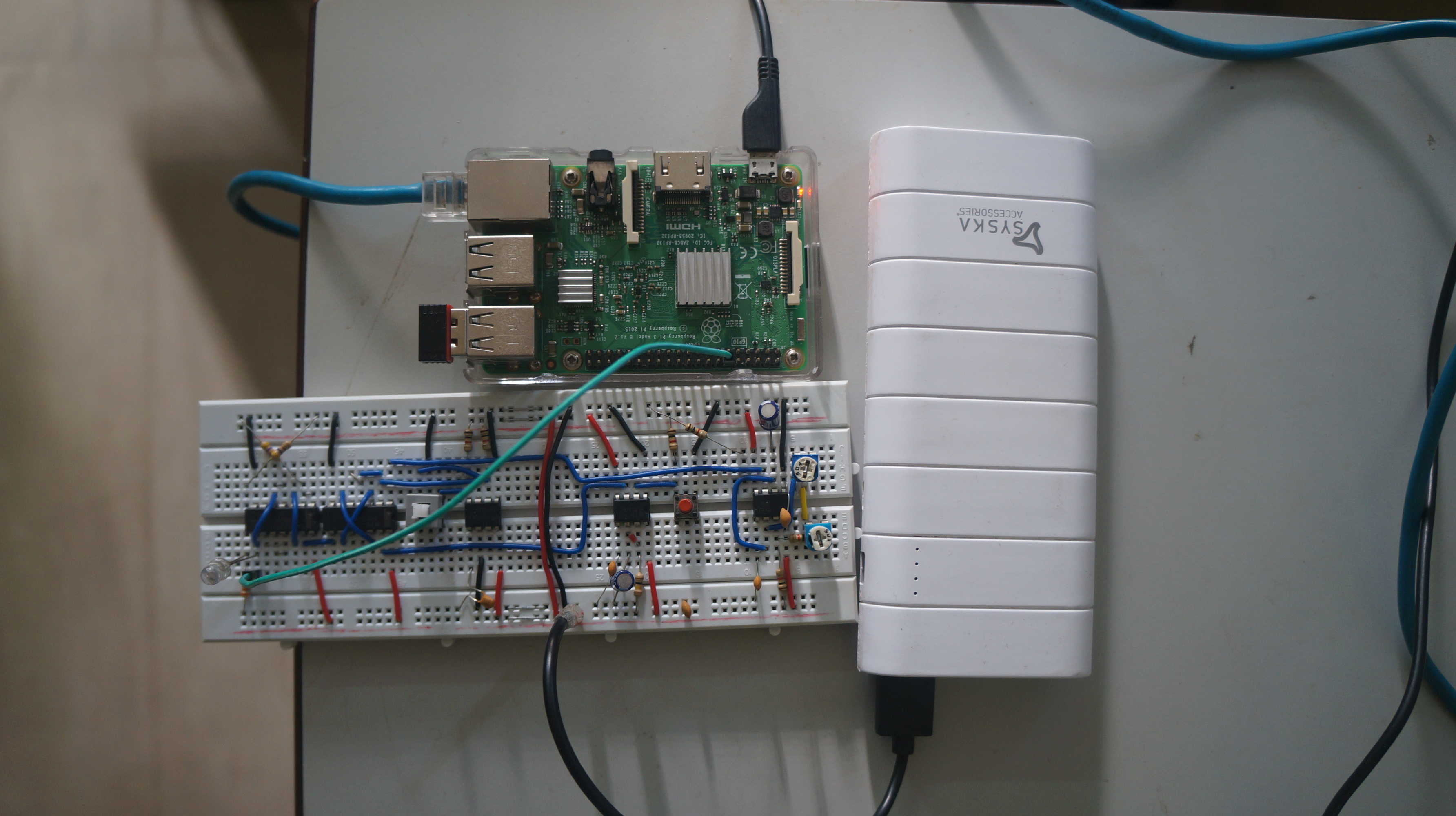
Also if this question is very noob I am sorry but I am still in high school.

\$\endgroup\$
6
  • 1
    \$\begingroup\$ what does IT WORKED mean? it works and it does not work does not describe what is being observed. \$\endgroup\$
    – jsotola
    Commented Dec 26, 2017 at 22:37
  • \$\begingroup\$ what frequency is being generated by the 555 timer? \$\endgroup\$
    – jsotola
    Commented Dec 26, 2017 at 22:38
  • \$\begingroup\$ Basically, I have no idea what is going on because your question is not that clear. But most likely your two circuits are grounded by way of some path you didn't think of. Like by way of their power supplies, or debug header connected to one or both boards, or something of that nature. \$\endgroup\$
    – user57037
    Commented Dec 27, 2017 at 4:16
  • \$\begingroup\$ It worked means that the pi could take an input from the circuit without having the ground connected! @jsotola \$\endgroup\$ Commented Dec 28, 2017 at 13:46
  • \$\begingroup\$ I used the power bank for that reason, the circuit was connected to the power bank and the pi was connected to the mains via a phone charger. @mkeith \$\endgroup\$ Commented Dec 28, 2017 at 13:48

1 Answer 1

0
\$\begingroup\$

That video is 10 minutes long so not many will watch it for you. A screengrab of the relevant part of the circuit would be good and a sharper photo.

Anyway, congratulations for realising that there should be a problem with the ground line removed. You may have enough capacitance between the two circuits to hold the grounds steady enough relative to each other to let it work - particularly if they're both close to a conductive surface. Try separating them or changing orientation and see if it still works.

Report back in your question.


How far do you think, should they be?

I would expect that capacitance would be very small at quite short distances - 10 cm, say. There will be a little capacitance to everything in its surroundings - including you. The input of your micro-controller is very high impedance (resistance) so it will be very sensitive to stray voltages. If you add a resistor from input to ground I think you will find that there isn't enough power in the stray voltages to turn on the input.

\$\endgroup\$
2
  • \$\begingroup\$ Hey thank you for your feedback. I have a question- How far do you think, should they be? @Transistor \$\endgroup\$ Commented Dec 28, 2017 at 14:04
  • \$\begingroup\$ See the update. \$\endgroup\$
    – Transistor
    Commented Dec 28, 2017 at 14:44

Your Answer

By clicking “Post Your Answer”, you agree to our terms of service and acknowledge you have read our privacy policy.

Not the answer you're looking for? Browse other questions tagged or ask your own question.