1
\$\begingroup\$

I've built a watchdog circuit for my Raspberry Pi using a NE555. In the astable configuration I'm counting ~5 minutes and then I kill the switch unless there is a signal from GPIO that discharges the C of the 555. I have a mosfet RFP70N06 with the gate directly connected to the OUT of the 555, and when C is 2/3 full out goes to GND, the mosfet is open and the power of the RPi is gone.
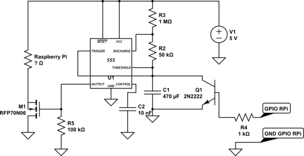
schematic

simulate this circuit – Schematic created using CircuitLab

My question is about the ground. The RPi does not initially share the supply ground as the rest of the circuit, since the GND of the supply of the RPi is on the Drain of the MOSFET. But then I'm using a GPIO pin, and I also used one of the GND pins on the header.

Since the RFP70N06 has an Rds=0.014 ohm I have my RPi with a 0.014 resistor on its ground, but from the GPIO header I have GND directly to the GND of the supply.

Does this makes sense? Should I be using an opto-coupler for the GPIO? I don't want a track on the PCB of the RPi being used as fuse.

\$\endgroup\$
8
  • 4
    \$\begingroup\$ Can you please include a readable diagram of your circuit in your post? The one in your link is badly formatted, and is upside down anyways. Click the icon of a circuit and pencil above your post to create and insert a circuit diagram. \$\endgroup\$
    – user39382
    Commented Jul 29, 2015 at 19:21
  • 3
    \$\begingroup\$ That is not a watchdog- if the GPIO gets stuck high it will never reset the micro. Also, switching the low side of the circuit like that is a recipe for tears. There's probably a way to make it work, but I can barely read your info so I'm giving up, sorry. \$\endgroup\$ Commented Jul 29, 2015 at 20:06
  • 1
    \$\begingroup\$ In addition to these issues, R PI is a computer and shouldn't just be shut off - this can cause read/write errors. It has a shutdown sequence for a reason. What are you doing with it that would require a watchdog timer? If it's low level control of things, an MCU is a much better option. \$\endgroup\$ Commented Jul 30, 2015 at 2:52
  • 1
    \$\begingroup\$ I agree with Kurt, but if you must use the RPi instead of a microcontroller I'd suggest getting the RPi to monitor a pin and when it goes high/low it initiates a shutdown. Just pulling the power on the RPi is asking for intermittent trouble. \$\endgroup\$
    – BenG
    Commented Jul 30, 2015 at 3:27
  • 1
    \$\begingroup\$ Problems with the circuit: 1) low side switching means your pi is floating. Might be tricky for interfacing to other things. 2) the GPIO ground will keep it powered, it bypasses your MOSFET! 3) watchdog needs to depend on action not just state. What if the Pi crashes while the pin is high? 4)no resistor between 470uF and 2n2222 might damage the transistor. Solutions: A) use high side switching. B) use an edge detection circuit to clear the timer. \$\endgroup\$
    – tomnexus
    Commented Aug 1, 2015 at 6:04

2 Answers 2

1
+50
\$\begingroup\$

Problems with the circuit:

1) low side switching means your pi is floating. Might be tricky for interfacing to other things. Generally, USB devices all should sit at ground potential.
Solution : high side switching with a P MOSFET.

2) the GPIO ground will keep it powered, it bypasses your MOSFET! Nothing wrong with powering the Pi from the 5V and GND pins on the GPIO header, by the way.

3) A watchdog needs to depend on action not just state. What if the Pi crashes while the pin is high? The watchdog won't reboot it.
Solution: have your timer reset by an edge, not a level. Another 555 will work, as a monostable they are edge triggered, not retriggerable. OR:
Use AC coupling of the pin through a capacitor, then rectify that.

4) You have no resistor between 470uF and 2n2222, so switching it on hard might damage the transistor. Add a small resistor.

Last comment - the Pi has an internal watchdog, have you considered using this? It seems you can operate the WDT manually, so it reboots unless you write to a system device within 10 seconds or so. So you can use it to reboot even if your Python program crashes, not just some esoteric system crash.

\$\endgroup\$
3
  • \$\begingroup\$ It seems that high side switching with P MOSFET I'd also need a NOT gate if I'd like to keep the current 555 logic. For a 555 I can not got lower than 50% duty cycle. About the "watchdog", I'm developing a C++ application that does signal processing from the sound card (AFSK software modem 1200 bps), and I also need internet access to relay received data. The issue I'm facing is that sometimes my cheap USB soundcard stops reading audio, and when I reboot the RPi it won't start. The embedded Watchdog is already enabled and useless. See github.com/raspberrypi/linux/issues/626 \$\endgroup\$
    – user2798
    Commented Aug 1, 2015 at 22:12
  • \$\begingroup\$ That's true, you'll need an inverter. It could be simply another small MOSFET and a pull-up resistor. \$\endgroup\$
    – tomnexus
    Commented Aug 2, 2015 at 6:29
  • 1
    \$\begingroup\$ You can go lower than 50% duty cycle if you use a diode across R2 - see the first circuit at williamson-labs.com/555-circuits.htm \$\endgroup\$
    – LeoR
    Commented Aug 5, 2015 at 14:44
1
\$\begingroup\$

What you have described won't work. That's because when you open the ground leg of the R-Pi, all of the output pins will float HI. This includes the GPIO pin that feeds Q1. Thus: Q1 turns ON, discharges the timing capacitor, which turns on MOSFET M1.

There are a couple of options you can explore.

1) Switch the R-Pi +Vdd pin instead of the ground. This is the preferred method for many reasons.

2) Use an opto-isolator where the opto's LED is driven by the GPIO pin (with suitable series resistor) and the opto's transistor discharges the timing capacitor.

My great preference is to do option (1) above.

\$\endgroup\$
2
  • \$\begingroup\$ What is the difference between switching GND vs +V on the RPi? Is the Rpi going to see different power? Will the MOSFET dissipate more power? I'm going with 1 for sure. \$\endgroup\$
    – user2798
    Commented Aug 1, 2015 at 7:35
  • \$\begingroup\$ P-Channel devices tend to have a bit more On resistance but I don't think it will be noticeable in most cases. \$\endgroup\$ Commented Aug 3, 2015 at 21:45

Your Answer

By clicking “Post Your Answer”, you agree to our terms of service and acknowledge you have read our privacy policy.