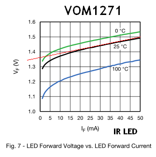
After establishing that we're not going to use our load bank in PWM mode (see here), I'm now trying to draft up a circuit that would be controlled by an µC (Arduino or else) and a multiplexer (this).
I'm also trying to protect the input from reverse voltage and overvoltage / making it able to cater with 1,8-24V digital input.
OK so here's my design thinking
- 1N4148 for reverse voltage protection
- 1,8V Zener diode for overvoltage protection (able to take 24V as a digital signal)
- Resistor for current protection (500R ==> 10mA@5V)
- This one I'm really not sure about : a 0,1µF in order for the whole contraption not to turn-off between two "cycles" of the multiplexer. I know that'd definitely be a no-go in a fast-switching application but that's not the case there... I'm also guessing that the MUX chip will not change an output state between two update cycles but...
 So anyway, I hope I'm not completely off on this and wait for your feedback.
So far what I take away :
- My // diode is useless
- I could use a P-channel transistor instead of a diode for reverse protection (avoids the diode Vf). Say something like this
But it also brings one question to my mind : would such an input protection be compatible with some high-speed input? Wouldn't the rise time of this p-channel transistor also add to the whole chain?
- I cannot use a resistor to limit the current since my input voltage has a wide range
Where I'm still lost :
- What should I use to limit current ? :-)
- Is a zener diode used this way (through it's breakdown voltage) will really work at 10-40mA? If I refer to the datasheet Zener diode datasheet the Vz is way above the nominal 1,7V when above it's nominal 50µA. It's way above 3V at only 10mA
- Would maybe just using a LDO such as this one solve all of that?
Thanks for the help!
Hi everyone,
OK so I'm still not confident in my zener overvoltage protection...
After some reading, I found that I have to make sure the zener is always going to be conducting some current or it might not be very effective at all... So I'm going to add another resistor in // with the zener to ensure this minimum current. Not just completely sure that's the right way to do it.

