14
\$\begingroup\$

Let's assume I have a microcontroller with some amount of peripherals attached and would like to be able to make a reasonable estimate of battery life. Because I might have it sleep at times, and various peripherals would be in differing states, my current consumption might vary between uA (in sleep mode) and some 10s of mA (when awake).

Now, I could attach a battery and let it run down and measure the time, but this makes it both time consuming and hard (and possibly expensive) to compare different approaches, both in the firmware and hardware.

I could place a multimeter in series, but even if it has data logging, that is at some interval and I'd have to interpolate, and could entirely miss variations smaller than the interval. (Plus burden voltage and all that.)

If my device sleeps enough, the awake current becomes somewhat negligible, but that might require a 1000:1 ratio of sleep time to awake time, so that's not likely on all designs.

Is there some device that integrates current over time at very small amounts (e.g., not the Kill-a-watt outlet meter)? Basically I'm interested to know that "over the last hour, 20mAh were consumed". Bonus points if I can get precision current measurements at any given time, to compare awake and asleep current consumption.

\$\endgroup\$
13
  • 3
    \$\begingroup\$ @Sparky256 what are you talking about? A 10 kHz sampling rate would very likely suffice here, assuming there's enough decoupling capacitors involved. Let's say we're using 16 bit per sample, that makes only 20 kB per second. Any modern 16 or 32 bit micrococontroller can write that to an SD card without much ado, and my PC can store years of that in RAM, on SSD or hard drive. This isn't the 1960s! Even Vince's 1MS/s is ... laughable for someone who's working with software defined radio. \$\endgroup\$ Commented Jan 8, 2018 at 22:29
  • 5
    \$\begingroup\$ @Sparky256, I have a 16 channel NI Labview system that can record 16 channels of 16-bit DAC readings at 200 ksps until the 1 TB hard drive is full. It's all about how much money you want to pay. \$\endgroup\$ Commented Jan 8, 2018 at 22:33
  • 3
    \$\begingroup\$ @Sparky256 certainly, name-brand DAQ cards are expensive. For this purpose, a very simple device would do – potentially even a sound card (with bridged coupling caps) with a voltage reference on the other stereo channel. \$\endgroup\$ Commented Jan 8, 2018 at 22:41
  • 4
    \$\begingroup\$ Excuse me, but integration does not need storing the digitized current samples, It's enough to save the cumulated integral - a sum. 1MSa/second or 1Sa/second, one second integrating time or one week, few bytes of memory is enough. \$\endgroup\$
    – user136077
    Commented Jan 8, 2018 at 23:01
  • 6
    \$\begingroup\$ I haven't seen anyone mention coulomb counters, which seem like a not-bad idea in this situation \$\endgroup\$
    – BeB00
    Commented Jan 9, 2018 at 0:42

15 Answers 15

14
\$\begingroup\$

Well, there's certainly specific current-sensing ICs. In your case, I'd "simply" go with something like:

  • Use a small (e.g. 0.5 Ω) series resistor between battery and your electronics.
  • Amplify the voltage across that resistor with an instrumentation amplifier
  • Log that voltage, e.g. using an ADC

Problems:

  1. low currents · low resistance = low voltage: Your measurement accuracy will be bad due to noise
  2. since microcontrollers wake up very fast and go to sleep equally fast, your ADC sampling rate necessarily needs to be very high.

But as a principle, that works, and is certainly viable (although designing a stable, low-noise, high-amplification instrumentation amplifier might be nontrivial; but: there's existing instr.amp ICs that make that a lot easier).

Luckily, your problem is rather common. So: Many, including Texas Instruments, have a portfolio of current sensing amplifiers, some of which integrate both aforementioned shunt resistor AND a digital interface. See TI's product listing.

In fact, these ICs are capable of measuring current and supply voltage at the same time – and that's great to actually measure drawn power, a measure far more relevant to battery life than raw drawn current, if there's nonlinear elements (that is, for example, MCUs).

The INA233, for example, can be connected to an external shunt (let's say, 0.3 Ω) and has a resolution of 2.5 µV per ADC step. That means, a single ADC step is I = U/R = 2.5 µV / 0.3 Ω = 8.333 µA in current.

I think that device also has an automatic sampling & averaging mode, so that you can easily get good approximations even under rapidly changing load.

Also, as I just found out: the thing has an "alert" level, so that you can wake up your measurement system whenever the current rises above a configurable threshold. Nice! That way, you only need to sample occasionally.

\$\endgroup\$
3
  • \$\begingroup\$ Could the need for a high sampling rate be alternately addressed with an analog integrator which is sampled then reset at a lower rate? \$\endgroup\$
    – Phil Frost
    Commented Jan 9, 2018 at 1:20
  • \$\begingroup\$ Note that no battery suppliers have the same leakage, capacity and double layer effect or ESR ratios. Hence predicting. Ah capacity vs current discharge is impossible to generalize. It must be tested unless specified precisely by datasheet. \$\endgroup\$
    – D.A.S.
    Commented Jan 9, 2018 at 1:34
  • \$\begingroup\$ @PhilFrost I like that idea, but am concerned about the also integrating inaccuracies! But I'm pretty sure that this, at least at some scale, is feasible! \$\endgroup\$ Commented Jan 9, 2018 at 9:22
8
\$\begingroup\$

Is there some device that integrates current over time at very small amounts

Yes, there are several; the oldest is an electroplating cell (the mass of plated metal represents the amp-hours)Edison patent, and electrolysis cells (gas accumulation into a capillary tube) have been used more recently. These are exactly equivalent to analyzing the battery after a long use period.

Nowadays, use digitization.

If you expect fluctuations faster than a digital sampling rate, that's fixable. A two-branch current path can be arranged, with high frequency conductance (a capacitor) that bypasses the current sensor, and a parallel low-frequency conductance (inductor and current sense element).

If you expect long-duration small current (that defeats digital sampling granularity), that's fixable, too. Add a small DC-plus-white-noise source to the DC current signal, and a fractional-bit amount of current will cause (statistically) a correct digital accumulation over large times. ADC with dither fig. 5a The DC part of the added signal must be calibrated away, though. Pseudorandom noise sources are useful for this kind of 'dither'.

Digitization and accumulation into a register (just like the Kill-a-watt) can work with easily available components, and some trickery tames its potential for mismeasurement.

\$\endgroup\$
7
\$\begingroup\$

Quick and dirty: SUPERCAPACITORS! (Also search ultracapacitor.) They'll power your system, and display the integrated current as a voltage-sag with time.

What processor Vdd, and/or battery volts were you contemplating? A capacitor naturally integrates current of course, and if you use a few-farads supercapacitor instead of a battery supply, you can measure the voltage falling over time, and precisely determine the longterm average microamps.

If your design needs a constant Vdd, choose a supercap value large enough that the voltage only sags XX percent while your test is running. Depending on average current, you might be able to get away with a few-dollars capacitor. For example, 4.7 farads at a few volts is a common supercap in surplus catalogs. (Sparkfun has some ten farad, and maximum size is Electronic Goldmine's 3000-farad boostcaps at 2.7V.) Stack 'em in series to get higher voltage limit.

\$\endgroup\$
4
  • 4
    \$\begingroup\$ Supercaps have significant leakage current changing with voltage and temperature, which the OP will have to account for. \$\endgroup\$ Commented Jan 9, 2018 at 8:30
  • 2
    \$\begingroup\$ @DmitryGrigoryev Good point. Run the test with bare capacitor alone, calculate the leakage current, then test again with cpu board attached. Don't forget: quick and dirty, not complicated and high-precision. If he needs to know the answer within 1%, then go to the well-designed active integrators, etc. \$\endgroup\$
    – wbeaty
    Commented Jan 9, 2018 at 22:34
  • \$\begingroup\$ Run the test several times, some with and some without the cpu board attached, in randomised order; then calculate the mean difference and its confidence interval. /statistician \$\endgroup\$
    – nekomatic
    Commented Jan 10, 2018 at 10:59
  • \$\begingroup\$ Then meta-analysis of multiple hobbyist cpu projects, to detect if any groups were creating bias by discarding outliers. \$\endgroup\$
    – wbeaty
    Commented Jan 10, 2018 at 20:23
4
\$\begingroup\$

If you are expecting a large dynamic range, an option could be using a current mirror flowed by a logarithmic trans-impedance amplifier like the LOG114. You can obtain more than 6 decades of range with a well-tuned circuit. Integration can be adjusted with a capacitor after the current mirror.

This is a more complex solution, and the resolution at high current, when the battery charge is significantly changed, is lower. The accuracy vs straight, proportional sensing will depends on the fraction of time you spend at low current.

Also, you can just go brute-force with the ADC resolution. 24bits or 32bits could cover 4 decades without issues.

\$\endgroup\$
3
\$\begingroup\$

For your rough measurements (maybe +/-10% or 20%).

Just put a resistor in series with the power and parallel it with a capacitor to yield sufficiently large time constant that your sample rate does not miss significant data. For example, if you are sampling at 100Hz you might pick a time constant of 0.2 second. Probably it will be an electrolytic capacitor and a low impedance type is best, and you can parallel it with 1uF-10uF ceramic if the pulses are shorter than about 10us. The value is non-critical, it just has to be high enough. Pick the resistor so that it doesn't drop too much voltage so as to affect operation yet yields enough signal that you can get a reasonable measurement.

There's no need to analyze the rise and fall times of amplifiers or any of that stuff- the resistor and capacitor will do the job.

Keep in mind that operation that depends on the battery being a low-impedance source to your "spikey" pulses will fail before the battery is actually exhausted- paralleling the battery with a capacitor can (sometimes greatly) extend the life- the battery internal resistance increases as it becomes exhausted.

\$\endgroup\$
3
  • \$\begingroup\$ also, keep in mind that if your on-times are short and your standby current is low, that it'll be a good idea to measure the current without your circuit attached, just to zero out the leakage of the electrolytic cap – I've roughly calculated MCU designs of sporadically active controllers, and the leakage through the 100 nF ceramic cap was higher than the average power consumption of the MCU. \$\endgroup\$ Commented Jan 8, 2018 at 22:55
  • \$\begingroup\$ @MarcusMüller Amazingly high- standard ones are spec'd at 500\$\Omega\$/F so about 500M for a 1uF (maximum, typical should be much less). I wonder if it was damaged. Or maybe you had an amazingly good MCU (deep sleep or something!). I guess in practice I don't worry much about less than a few uA because even a button cell has much more self discharge than that. \$\endgroup\$ Commented Jan 8, 2018 at 23:01
  • \$\begingroup\$ yeah, it's a couple of years in the past. But, maybe, it was damaged (though I'm not sure what kind of damage would increase leakage so significantly. Makes you wonder whether I had a systematic error somewhere). MCU was some freescale ultra-low-power thingie that was on at lowest clock speed for a couple dozen µs before turning completely off (excluding RAM and an interrupt source), mostly for seconds to minutes. Never-finished prototype for IR-communicative "jewelry". \$\endgroup\$ Commented Jan 8, 2018 at 23:11
3
\$\begingroup\$

What I propose is probably overkill... But if you find that the standard/cheap solutions just don't have sufficient dynamic range, or if you do these kinds of measurements regularly, you may want to look at this very neat device: The RocketLogger.

It's developed and open-sourced by ETH Zurich. They call it a "Precision Mixed-Signal Data Logger for Portable Measurements". It's a portable current and voltage logger with a very high dynamic current range, based on a Beaglebone SBC.

  • 2× Current Channels with high dynamic range from 4 nA up to ±500 mA
  • 4× Voltage Channels measuring from 13 uV up to ±5.5 V
  • etc...

Disclaimer: I'm not associated with the creators of the device.

\$\endgroup\$
3
\$\begingroup\$

Coulomb counting may be done by measuring the change in stored charge by voltage drop from a known charge Q=CV over the measured interval of at least 1 repetitive cycle.

Firstly the battery life must be defined in terms of a minimum in units of watt-seconds or Joules so that the total charge life energy needed can selected.

Secondly, the Coulomb counting method must be accurate enough by some test method in short intervals such as 1 hour or so if this can average repeating cycles of sleep and pulsed activity so that software efficiency may be optimized for energy.

The battery storage life might or could be for example; 1 yr primary or 1 day secondary between charges but ought to be spec’d.

Thirdly, Could we use a low leakage cap to count Coulombs faster? Such as in 1 hr?
If drain was expected to be 20mA per h avg and drop only 0.1V what value C is needed? C=Ic*dt/dV = 20mA*3600s/0.1V=700 Farads

If possible choose a part with this range of capacitance such as a 3V CR123A battery then verify the coulomb counting method and monitor voltage.

Alternatively sense current and use current content to accurate count Coulombs separately from the design.

\$\endgroup\$
3
\$\begingroup\$

The one hour part of your question makes this a bit difficult - but maybe you don't actually need it if your device is doing something cyclic (like most embedded stuff does).

So lets go complete overkill just to show what you could buy. The Keysight CX3300 will allow you to sample current waveforms with up to 200 MHz analog bandwidth and 1 GSa/s. Combined with 256 MSa of memory, you can get decent sample rates even over an hour. Price is of course a bit high starting at $33,000 and the probes starting at $4,800.

A bit of a cheaper road I'm usually going is using my oscilloscope with a current probe like the N2820A - this will set you back around $4,200 and you don't get quite the analog bandwidth (up to 3 MHz) but I find this really usable. This will give you a channel with low current measurement and one with high current measurement, so the analysis needs a bit of manual calculation.

I'm sure there are similar offerings from different manufacturers for something like the above mentioned Keysight products.

As my oscilloscope doesn't come with a massive amount of memory what I usually do is measure one cycle of the activity and calculate from there - our devices don't have long cycles, so that works out quite well.

If I need to do a long time measurement with automatic Wh calculation, I use my trusty Gossen Metrahit Energy, which does a great job even with low currents. But the datalogging is not suitable for highly variable currents as the sample rate is not that great.

Please don't misunderstand this answer as me boasting about some expensive equipment, it's a pointer that there is professional test equipment out there which can handle the requirements - as most of the other answers focus on doing it on your own (which might cause trouble if you are not just performing happy tests for your own).

I'm not affiliated with Keysight or Gossen in any way, I'm just a happy user of their products.

\$\endgroup\$
2
\$\begingroup\$

Take @marcusmuller's excellent answer and feed the output into an integrator. zero the cap before you start, and measure the accumulated mAh or uAh as a DC voltage.

You may have to experiment with your integrator capacitor selection; some capacitor designs are bad for soakage or have internal resistance which prevents them from correctly zeroing.

\$\endgroup\$
2
\$\begingroup\$

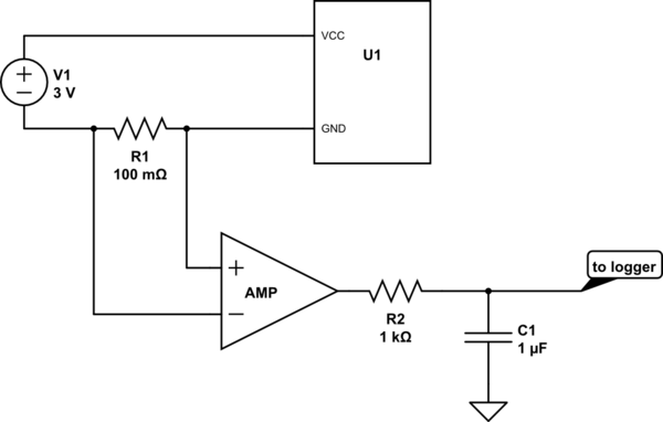
I could place a multimeter in series, but even if it has data logging, that is at some interval and I'd have to interpolate, and could entirely miss variations smaller than the interval.

So, you can put a low-pass filter in your measurement chain to log the mean value at a reasonably low frequency:

schematic

simulate this circuit – Schematic created using CircuitLab

\$\endgroup\$
2
\$\begingroup\$

For shorter durations (seconds) you could use a device like the μCurrent connected to an oscilloscope.

If your peak current is relatively unimportant (for example because it’s very short or because it’s dominated by a more or less fixed and known value like your microcontroller’s peak current) you could use a shunt resistor with a diode in parallel to limit the voltage drop. With a 100Ω shunt and an SI-diode in parallel you could measure up to ~7mA and achieve accuracy in the tens of μA.

\$\endgroup\$
2
  • \$\begingroup\$ It is much better than seconds. The analog bandwidth is 8 kHz for the original μCurrent and 300 kHz for μCurrent GOLD (the Kickstarter one). I have measured 1 ms current transients for a Raspberry Pi using this setup. \$\endgroup\$ Commented Jan 9, 2018 at 22:43
  • 1
    \$\begingroup\$ @PeterMortensen: I meant for the total duration you can measure in order to estimate battery runtime (i.e. average power over time). If OP’s device performs things like e.g. periodic measurements in 0.5s intervals then it would be sufficient to measure for a few seconds. If OP’s device performs more complex tasks over longer time then he/she would need a different approach. \$\endgroup\$
    – Michael
    Commented Jan 10, 2018 at 14:57
0
\$\begingroup\$

I think your idea of using a battery might be the best approach, but I am not sure why you say it is hard or expensive? I am sure there are A-Hr meters you can buy but they may not measure accurately the short intervals of current you are interested in. Another approach would be a current probe connected to an oscilloscope. This would probably be the most accurate way to characterize the current in terms of amplitude and time but would not give A-Hrs unless your current waveform is periodic.

\$\endgroup\$
5
  • \$\begingroup\$ Let's say I want to see the impact of the latest code push on battery life on a device designed to run for ~2 months on a single battery. I need to sit there and let a battery run down for quite a while. :) ("Expensive" is for some definition if primary cells are in use.) \$\endgroup\$
    – David
    Commented Jan 8, 2018 at 22:37
  • \$\begingroup\$ One option would be to use a much smaller battery. As long as the A-hr of the battery is know you could scale the results to any size battery. \$\endgroup\$
    – EE_socal
    Commented Jan 9, 2018 at 0:03
  • \$\begingroup\$ Batteries are not calibrated measurement equipment. All you know about a 1Ah battery is that there's at least 1Ah in it. \$\endgroup\$ Commented Jan 9, 2018 at 8:22
  • \$\begingroup\$ The battery could be calibrated by putting a know load on it and see how long it takes to discharge. I agree it is not the most accurate method but maybe good enough. \$\endgroup\$
    – EE_socal
    Commented Jan 9, 2018 at 16:54
  • \$\begingroup\$ @EE_socal In a hobby project, sure. At work, I'd rather buy proper measurement equipment than pay an engineer for doing something as riveting as calibrating a battery. New batteries may change their characteristics after a few cycles, so calibrating one is not that quick. \$\endgroup\$ Commented Jan 10, 2018 at 9:35
0
\$\begingroup\$

I had to work through this problem a long time ago with lithium batteries. The device woke up for a very small amount of time, once per minute. I could sample the voltage across the battery. The problem with lithium batteries in this situation is that they have a very sudden 'knee' in their discharge cycle and when they hit that point, you're about out of time, and it's a small value range.

\$\endgroup\$
0
\$\begingroup\$

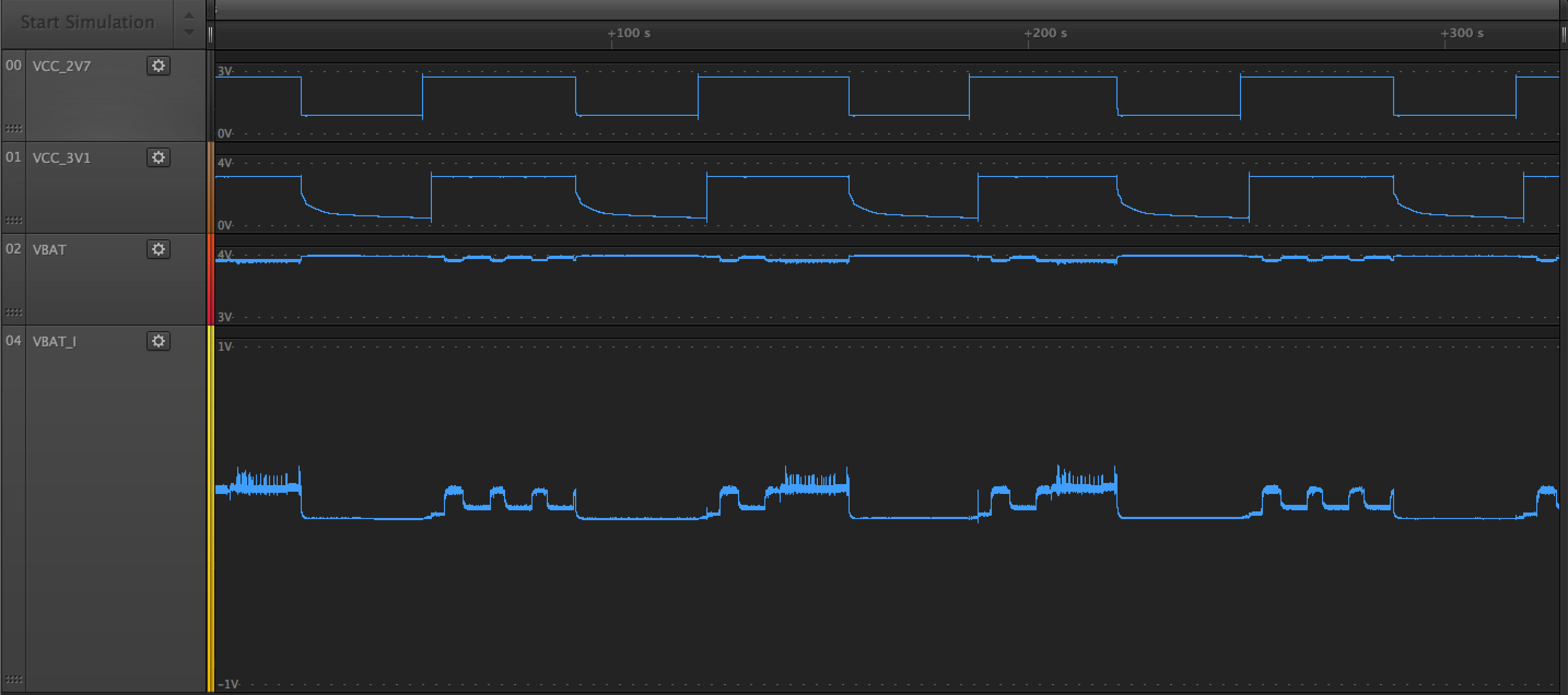
I’ve actually taken a logic/analog analyzer (Saleae Logic 8) and hooked it up to a µCurrent Gold and measured the whole current plot and battery voltage from fully charged all the way to discharged. You can simply run a python script that connects to the development interface to poll and store values. This does create a TON of data and often can’t easily be manipulated in Excel but you can at least open up a chunk of time to see what instantaneous current was at that particular time.

Here’s a screenshot from some battery life validation I was doing that looks similar to what you’re looking for:

Current Capture using Saleae Logic 8

The yellow signal is the current (V translate to A). You can see the battery response (battery hapened to be above the max 5V of the Logic 8 in this case) Then, most importantly, you can see the power rails coming on and then turning off for measurements (I was actually sending data via CAT-M to our cloud servers). For your case, you likely wouldn’t see as much exciting stuff due to the fact that your duty cycle is much smaller (I was doing some accelerated battery testing here that’s why it was so frequent)

If you want to see what my setup looked like, I wrote an article recently on how to take measurements with the gear I had that produced the capture above.

You can likely do something similar with a GPIB controlled osciliscope or different brand datalogger. I just happned to use what I had on hand.

For extended captures you can also check out the Saleae programming reference for their logic analyzers. I also created a gist of the code I used to create that capture as well here.

\$\endgroup\$
0
\$\begingroup\$

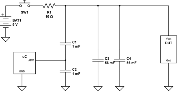
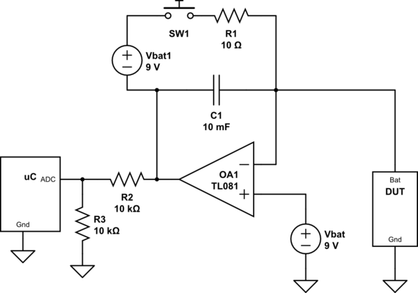
All these answers and only @wbeaty mentioned the obvious one. A device that integrates current with time? What about I = C dV/dt?

If the current consumption is low enough, a few capacitors might be more than enough but a super capacitor would be needed for higher currents. Adjusting the capacitors to obtain a reasonable drop in a reasonable amount of time. A circuit like the one below would do the trick.

schematic

simulate this circuit – Schematic created using CircuitLab

The capacitive divider is there to avoid removing current from the node. It can be pre-charged to the supply of the uC via the peripheral pin to establish the initial condition, and then periodically measured to read the rate of discharge. One problem with this circuit is that the output voltage will change, which could mean a variable load.

To avoid this problem, and for an adjustable all-purpose circuit with reasonable size components, an active capacitance multiplier could be used instead, like the conceptual schematic below. Some calibration with known loads, and you have a custom-made consumption-meter.

schematic

simulate this circuit

\$\endgroup\$

Your Answer

By clicking “Post Your Answer”, you agree to our terms of service and acknowledge you have read our privacy policy.

Not the answer you're looking for? Browse other questions tagged or ask your own question.