1
\$\begingroup\$

I have an early 1960 Silvertone transistor radio that I'm trying to convert to a guitar amplifier for a cigar box guitar, aka a CBG. (CBG's are typically built with primitive equipment and the inherent distortions and defects are considered part of their charm.)

The old radio works fine, I put 6 D-cells into it and I can pick up AM stations just fine.

Instructions for conversion are all over the web but basically consist of this:

  1. Ground one wire from the guitar cord to ground on the radio.
  2. Find the volume pot.
  3. Attach the other lead from the guitar random posts on the volume pot and strum until you hear your guitar through the speaker.

We're not talking rocket science here.

Now my radio has 2 concentric pots, one for volume and one for tone. I've been able to identify the volume pot by hooking up my Ohm-meter and turning the volume knob.

Now the problem is, when I attach the leads from the guitar I don't hear the string from the radio's speaker.

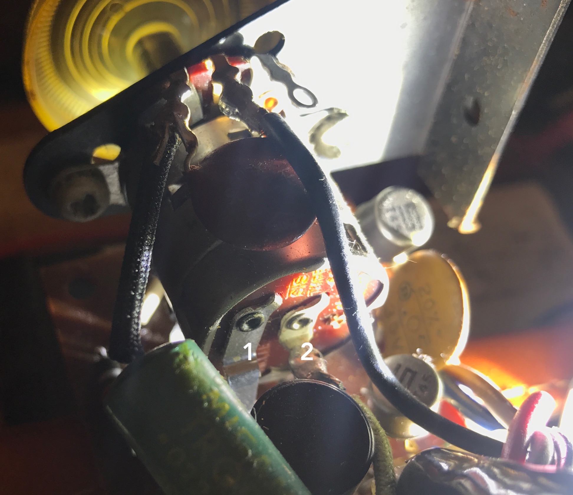
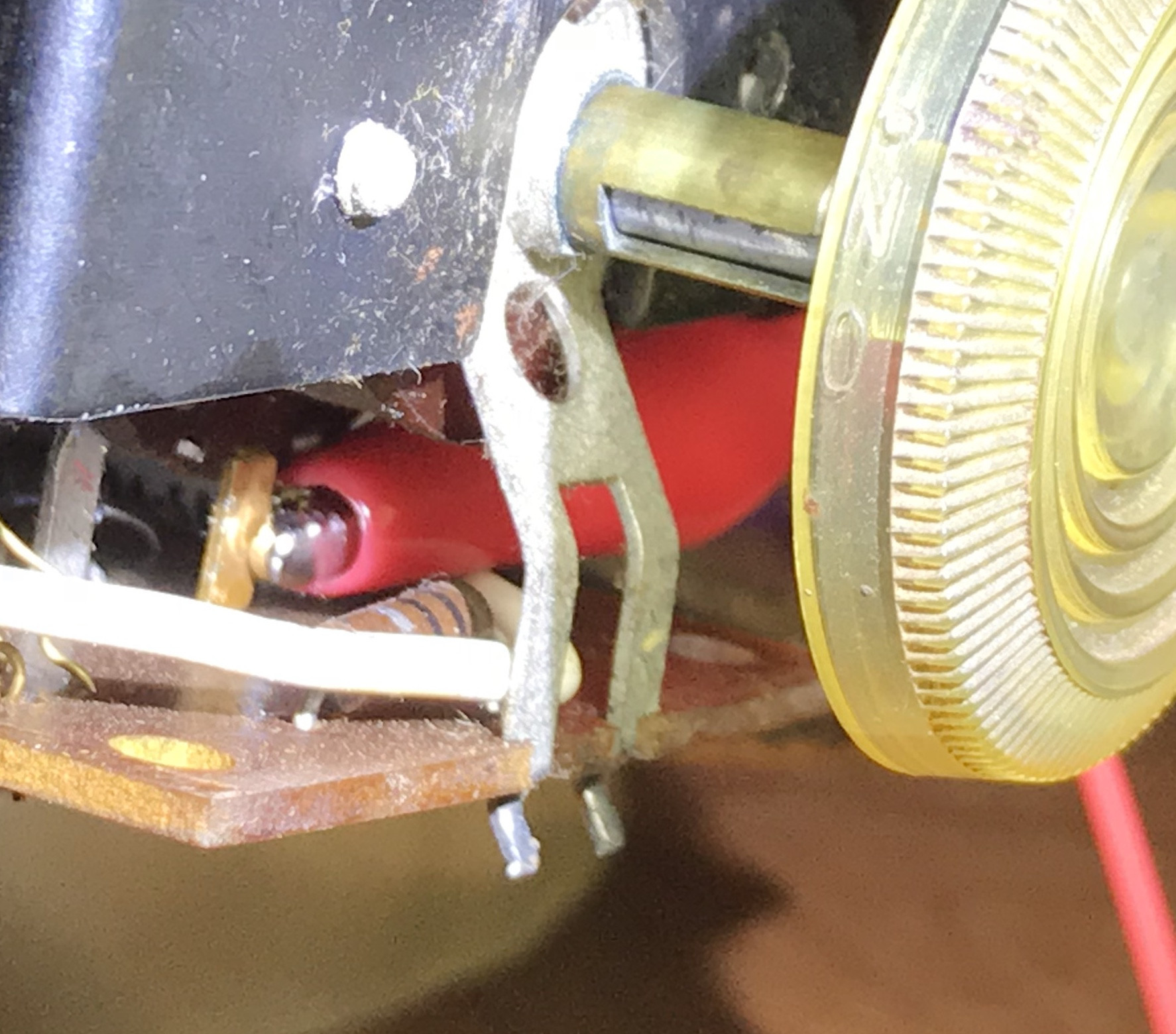
Here's the back of the volume pot:

enter image description here

Tap 1 has 9v when the volume control is clicked on, 0v when off. Tap 2 has 9v all the time. So it's clearly the power switch.

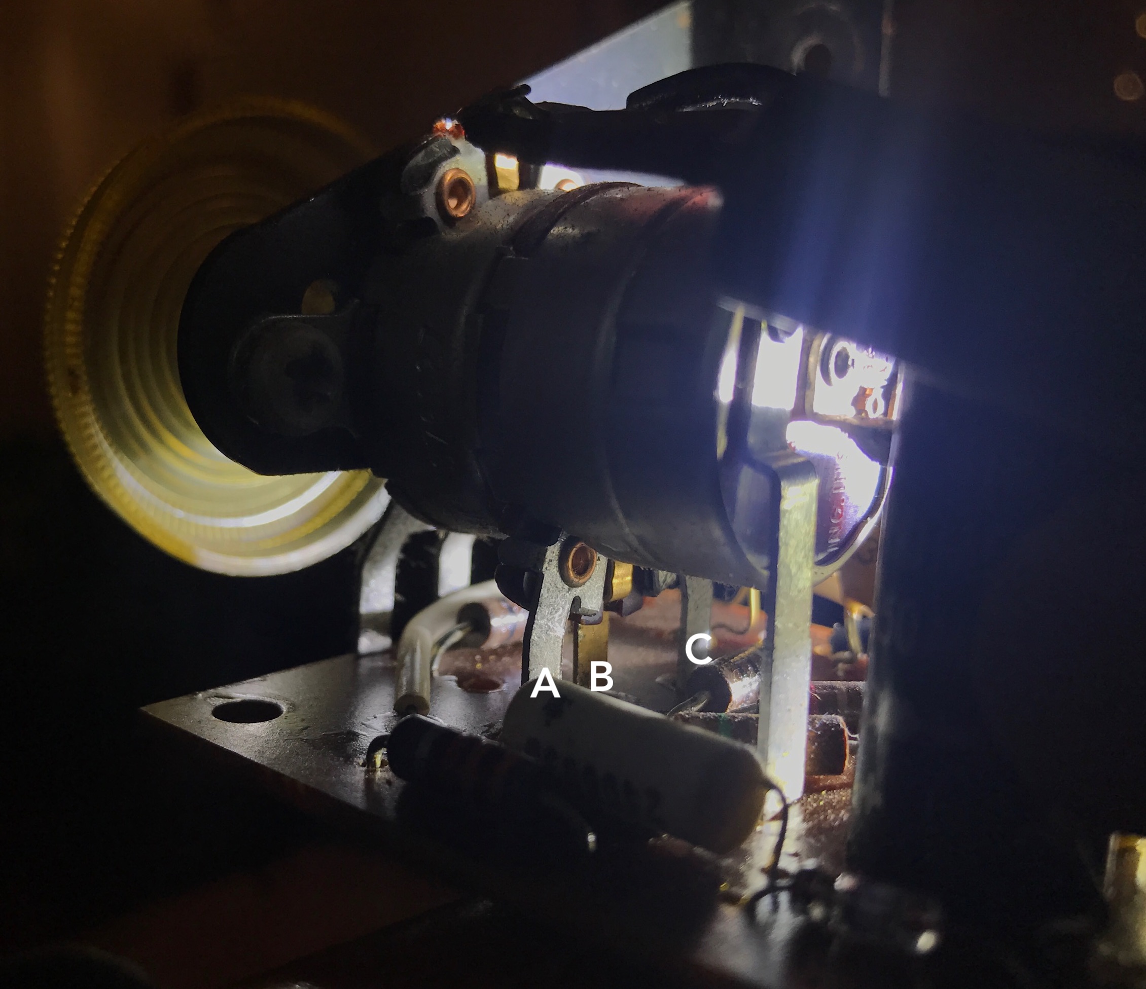
Underneath we find 3 more posts:

enter image description here

Taps A, B and C also have 0v when the volume is off, and 9v when the volume is on.

I pull the batteries and measure resistance (and yeah, I know, the pot is in the circuit so it isn't accurate but I'm just trying to find the "input" lead.

A always reads 4k Ohms, B varies from 2k to 4k, C is at 2k no matter what I do with the volume knob.

1 in always at 2k Ohms, 2 is 0 Ohms when off, 2k when on (which makes sense since it is connected directly to the battery)

So it seems to me that I should be hooking into tap B. So when I hook the rod-piezo to B and to ground I still hear the static of the radio and when I pluck the string, I do not hear the note out the speakers. One member of the cigar box forums said that the rod piezo pickup might not put out enough power, so I tried a wound magnetic pick and got the same results.

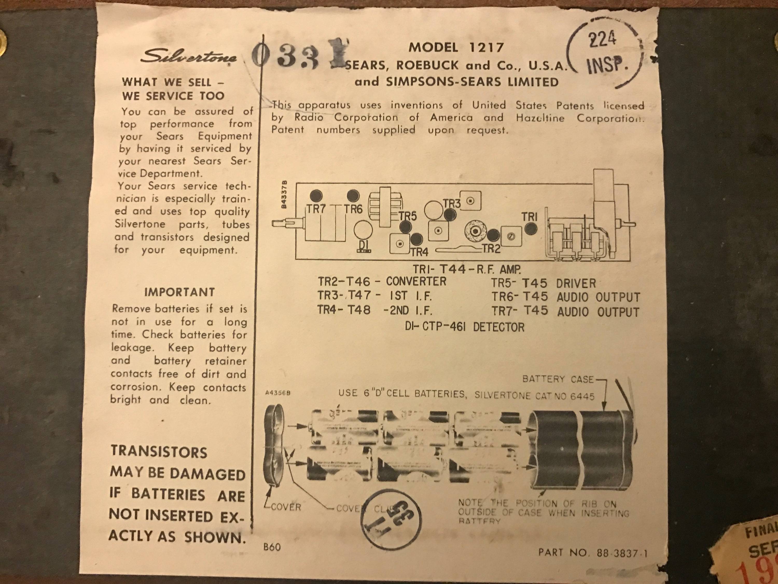
And here's the 'schematic' of the radio: (ok, so it is just a parts list...)

enter image description here

All the online tutorials make this look easy, but I'm baffled at this point. And go easy on me, my degree does have an EE in it, but it also has a CS in it and I do CS stuff for a living, that EE was really a long time ago...

Bonus question: I'd love to know why this works, it seems to me that I'm mixing the guitar signal with the radio signal but all the web instructions just say that you don't hear the radio.

Bonus question #2: Just how would I find and cut out the radio section? I'm guess that once I find the right place to tap into I just cut there to remove the radio from the circuit, is it really just that easy?

Update

I have something which may be the real schematic! The radio is almost certainly a Silvertone 700. See https://www.radiomuseum.org/r/sears_roeb_silvertone_700_1217.html

Hopefully this helps!

Note: It turns out this is not the schematic since it is 6v, not a 9v circuit. Thanks to glen_geek for pointing this out.

enter image description here

Update #2

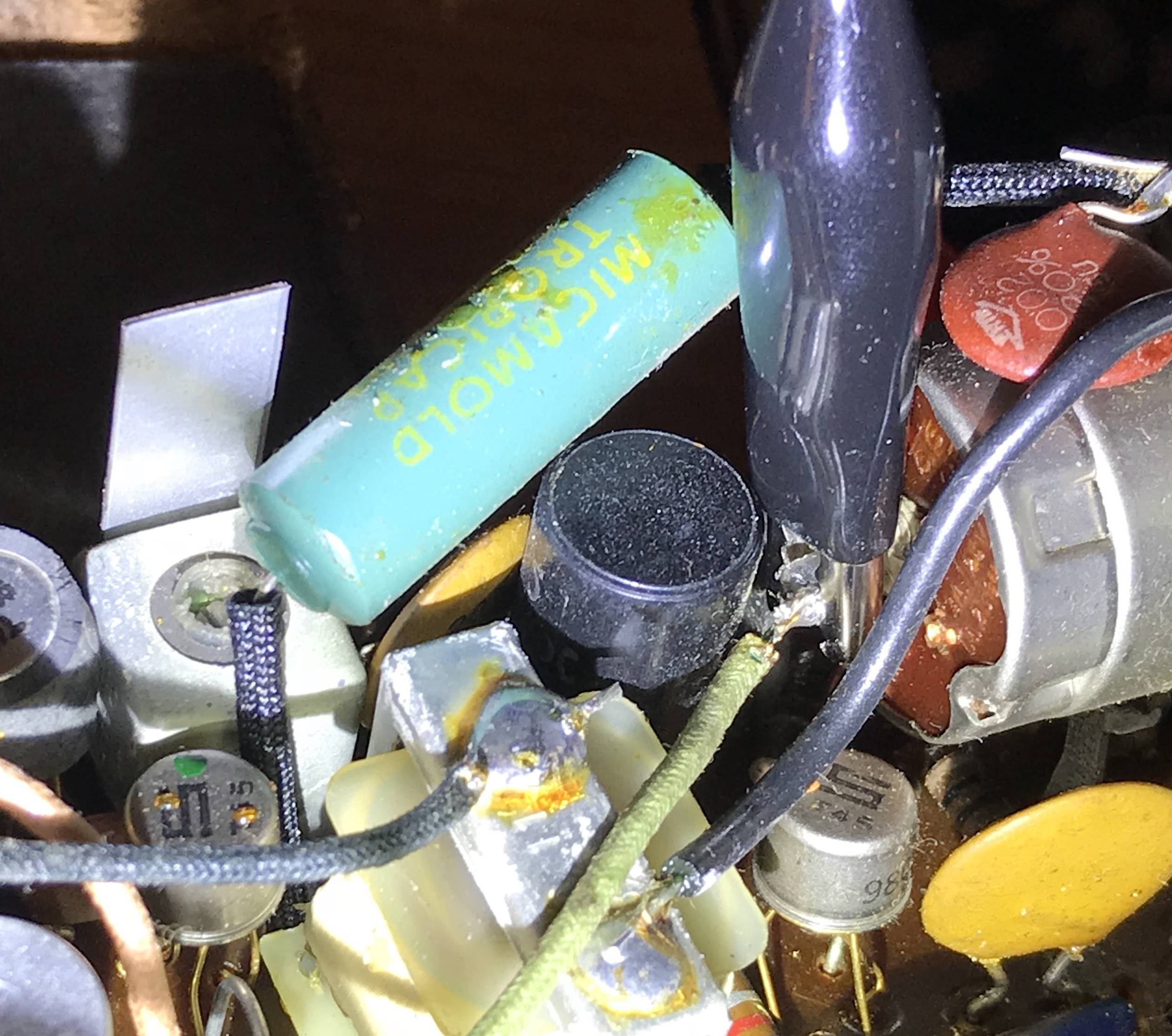
Here's some photos showing the connections. First, the battery has a green and black wire coming off it. With the VOM's black on black, and the VOM's red on green, I get 9VDC.

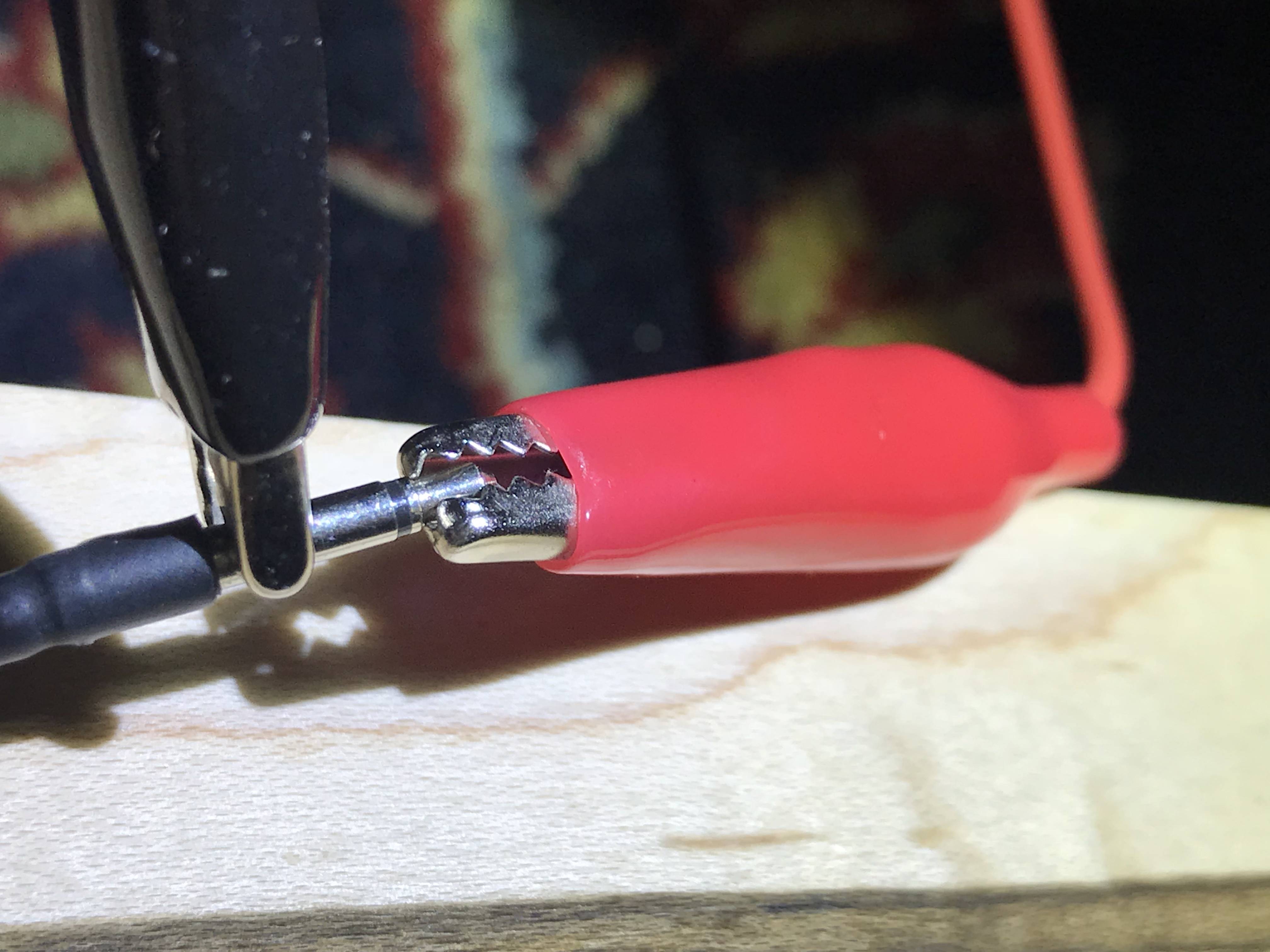
Here's the connection to the pickup:

enter image description here

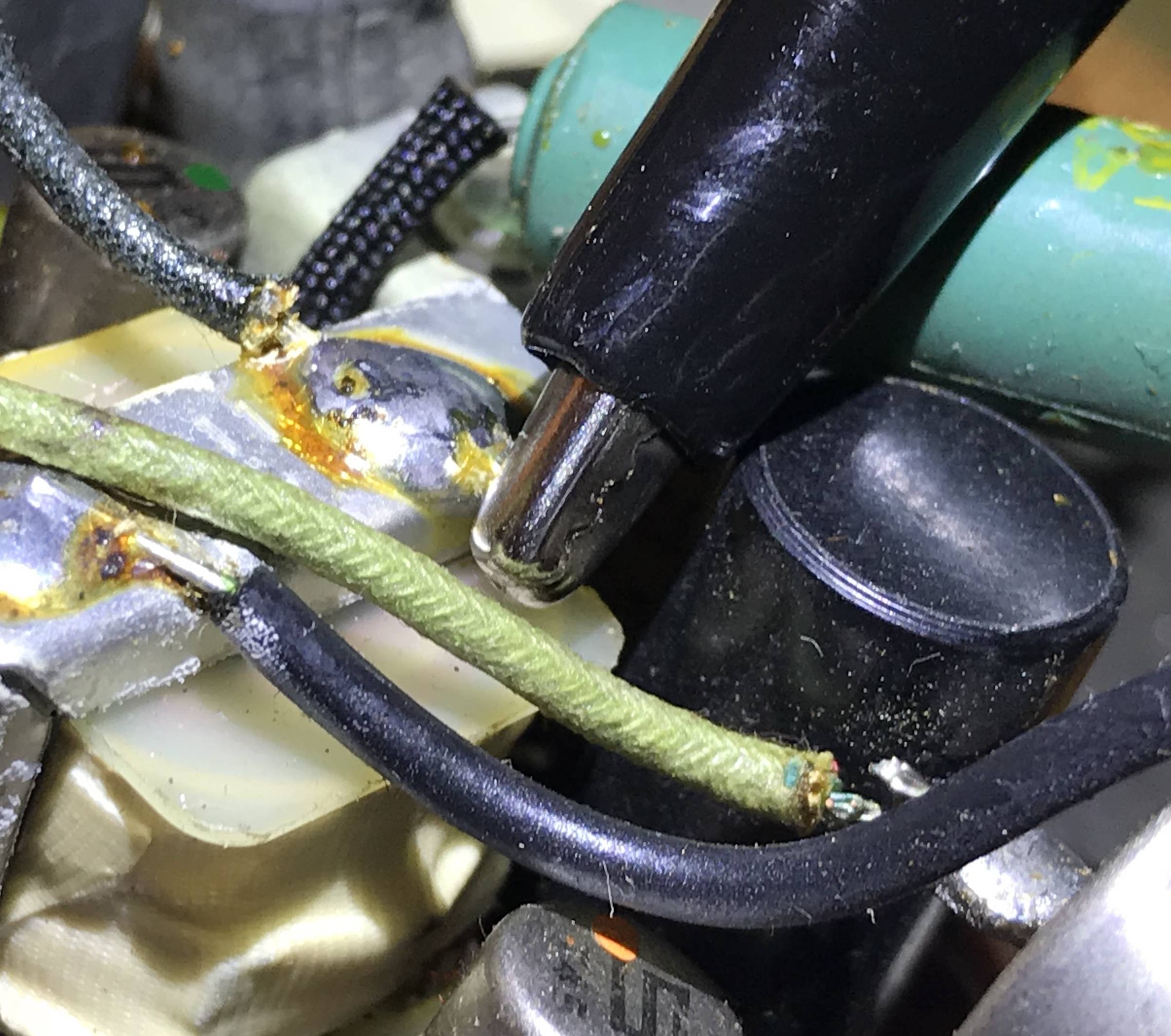
And my connection of the positive ground (green) wire. (The green wire goes directly to the battery pack's green wire, it's actually the same wire.)

enter image description here

And the connection to the center tap of the volume pot, B, in the above diagram, which should be the + side of C10.

enter image description here

And just for grins I put the ground to the other wire off the battery.

enter image description here

\$\endgroup\$
17
  • 2
    \$\begingroup\$ @PaulCezanne: Some radios may amplify a signal some before the volume pot, and then amplify it some more afterward. The strength of the signal from the guitar may be much lower than what the radio is expecting from its first amplifier stage. If you don't understand how amplifiers work, I'd suggest either buying some kind of pre-amp or trying a different radio until you find one that works as desired. \$\endgroup\$
    – supercat
    Commented Jan 19, 2018 at 0:11
  • 1
    \$\begingroup\$ Alas that is not a schematic \$\endgroup\$
    – τεκ
    Commented Jan 19, 2018 at 0:12
  • 1
    \$\begingroup\$ @PaulCezanne - A buffer essentially isolates two circuits from each other. Got any guitar pedals you could put in between your CBG and the radio? That will achieve the same effect. \$\endgroup\$
    – vofa
    Commented Jan 19, 2018 at 0:36
  • 1
    \$\begingroup\$ If your schematic is correct, you should tie the ground of the guitar to the positive terminal of the battery. You have to be old, but back in the day of germanium transistors, PNP was king and ground was positive. \$\endgroup\$ Commented Jan 30, 2018 at 22:10
  • 1
    \$\begingroup\$ One other point: the 5k pot puts quite a load on the pickup. Most guitar amps have, I think, > 100k input impedance. The 5k might attenuate the pickup signal too. \$\endgroup\$
    – Transistor
    Commented Jan 30, 2018 at 22:45

5 Answers 5

2
\$\begingroup\$

A rod piezo (or any piezo) has very high impedance: it puts out a good voltage signal but at very tiny currents. It will not be able to drive the common-emitter input stage of that radio's audio amplifier.

You would need to switch to a magnetic pickup, or add a buffer stage so this amp does not load down the pickup. A common simple circuit is to use a JFET preamp.

[JFET preamp[1]

This was from http://www.till.com/articles/GuitarPreamp/

This is a very common circuit and used for things like buffering a condenser (aka electret) mic capsule to drive a standard audio input.

Essentially no current is taken from the signal input since the junction is back-biased. The JFET converts the signal voltage into a modulated current through R3.

\$\endgroup\$
1
\$\begingroup\$

The two terminals you marked as "1" and "2" are the off/on switch.

The terminals you marked "A","B","C" are for the inner of the two concentric knobs. "A" should be the clockwise terminal, "B" is the wiper (moving contact), and "C" is the counter-clockwise terminal.

There are another set of three terminals, closer to the front panel, shown in the first picture above the pot (not connected directly to the circuit board), for the pot operated by the outer knob.

You should connect your guitar signal to the clockwise terminal of the volume pot.

\$\endgroup\$
2
  • \$\begingroup\$ But when I do that I don't hear the guitar out the speaker. But, you've spoken authoritatively, which is good, so I can hook up there and test other bits, like maybe I don't have a good connection or something. Narrowing the failure tree is good. \$\endgroup\$ Commented Jan 19, 2018 at 1:09
  • 2
    \$\begingroup\$ @PaulCezanne People who sound authoritative can still be wrong sometimes, so don't completely discount the possibility. (I'm not saying this is wrong) \$\endgroup\$ Commented Jan 30, 2018 at 21:46
1
+50
\$\begingroup\$

Why this works: In your schematic, diode D1 is a rectifier that turns the amplitude modulated signal to a varying DC voltage in the low audio range (< 5 KHz). You would put your signal on the "+" side of capacitor C10; Q4, Q5 and Q6 are the audio section. Your guitar only has to overdrive the diode and capacitor signal after it has been attenuated by the pot. Put the pot about half scale to give the highest impedance.

Your signal must be with respect to ground, which is the positive battery terminal on your schematic. Tie the ground of the guitar to the positive terminal of the battery.

\$\endgroup\$
8
  • \$\begingroup\$ It looks like that is the same as Point B in my photos, right? The + side of C10 is connected to the center tap of the volume pot. Right? Sadly, not working... \$\endgroup\$ Commented Jan 30, 2018 at 23:07
  • \$\begingroup\$ DO you have guitar ground tied to the plus side of the battery? \$\endgroup\$ Commented Jan 30, 2018 at 23:34
  • \$\begingroup\$ see connections photos in the posting, just added them. \$\endgroup\$ Commented Jan 30, 2018 at 23:40
  • \$\begingroup\$ Great! No response regardless of the position of the pot? \$\endgroup\$ Commented Jan 30, 2018 at 23:54
  • \$\begingroup\$ I would put the pot at mid-range, then use your test lead to short out the wiper to each side of the pot. If you have the right one, one side should give you full volume and the other should be mute. \$\endgroup\$ Commented Jan 30, 2018 at 23:56
1
\$\begingroup\$

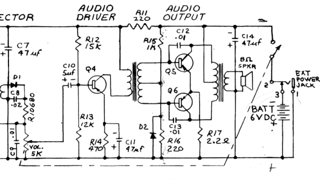
Fortunately you have a schematic. That makes this pretty straight forward. The important part of the schematic is:

One important thing to notice is that this is a positive ground system. The positive end of the battery is actually ground. When the power is turned on, it is negative relative to ground.

Everything to the right of where it says "VOL. 5K" is just a audio amplifier. You can use it as-is. You have to disconnect it from the radio receiver part, then connect it to this guitar thing.

It seems you have already found the wiper of the "VOL 5K" pot. The end that is permanently connected to the + side of the battery is ground. The other end is where you want to connect your audio signal to. Before you do that, remove whatever else is connected to that end of the pot.

With nothing connected to the audio input end of the pot, you should be able to crank the volume to maximum, then hear some hum when you touch that point with your finger. That's a good test that everything else is basically working.

This audio input is already AC-coupled due to C10. You can therefore just bring out two wires from this radio, which are the two fixed ends of the pot. Any audio you put on those two wires will come out the speaker, subject to the setting of the volume control.

\$\endgroup\$
1
  • \$\begingroup\$ So physically cut the correct tap on the volume pot (to remove the radio from the circuit) and then hook up there? I've not cut anything yet. Also, it is hard to tell if it is A or C in my photo. (And sadly, the schematic is wrong, 6v, not 9v) \$\endgroup\$ Commented Feb 6, 2018 at 2:16
0
\$\begingroup\$

The problem you are facing seems to be 'impedance matching'. The audio amplifier section seems to be having a low impedance which is not matched with high impedance output of the guitar. I can suggest you to do following,

  1. Change C10 value 5uF to 1uF or 0.1uF . This may increase the input impedance.
  2. Try removing the connection to the volume controller from C10 and directly connect to guitar.

Whoever drew this circuit has changed the polarities upside down. (+) in bottom and Ground in top. Pay special attention to this. Connect your guitar to C10 and the upper wire of the circuit.

Hope this will fix your problem :-)

\$\endgroup\$
1
  • 2
    \$\begingroup\$ "Whoever drew this circuit has changed the polarities upside down. (+) in bottom and Ground in top." No, it is positive ground - see the jack socket sleeve connection, the potentiometer grounds and R11 in the negative supply. We would probably, these days, invert the whole drawing so that the most positive rail was on top. \$\endgroup\$
    – Transistor
    Commented Feb 5, 2018 at 19:11

Your Answer

By clicking “Post Your Answer”, you agree to our terms of service and acknowledge you have read our privacy policy.

Not the answer you're looking for? Browse other questions tagged or ask your own question.