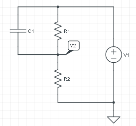
The answer is in Thévenin, like Alfred and jippie also suggested. Thévenin claims that any 1-port network consisting of voltage sources and resistors can be replaced by a voltage source and a series resistor across that port, and who am I not to believe him?
Let's consider your circuit without the capacitor and assign its connections as the circuit's port.
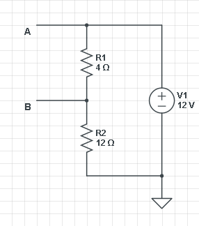
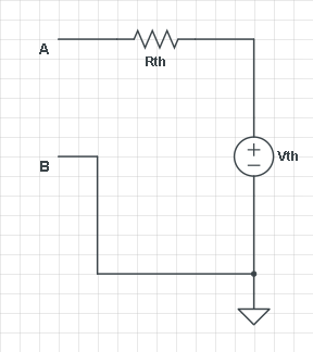
First we look for \$V_{th}\$, which we do by leaving the output open-circuit, so that \$R_{th}\$ can't cause a voltage drop. Then R1 and R2 form a voltage divider with \$V_{AB}\$ = V1 \$\times\$ R1/(R1 + R2) = 3 V. (I'm using actual values for voltage and resistors to make it more graphic.) That's \$V_{th}\$. Fine.
Next we have to find \$R_{th}\$. You can do that by shorting all voltage sources and measure the resistance between A and B. But let's do it the alternative way: short-circuit A to B, and measure the current through that point. That should be \$V_{th}/R_{th}\$. Both methods give the same result, and it depends on the kind of circuit which way is best.
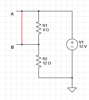
So shorting A-B we get I = V1/R2 = 12 V/ 12 Ω = 1 A. (What a coincidence! :-)) Then \$R_{th}\$ = 3 V/ 1 A = 3 Ω. If we now reconnect our load we have the typical RC circuit where C1 is charged via a series resistor (let's say C1 is 1 F):
\$ V_C(t) = V_\infty + (V_0 - V_\infty) e^{\dfrac{-t}{RC}} \$
\$V_\infty\$ is \$V_{th}\$ because after C1 is charged there won't be a voltage drop across \$R_{th}\$. And \$V_0\$ is 0, we start with an uncharged capacitor. Then
\$ V_C(t) = 3 V + (0 V - 3 V) e^{\dfrac{-t}{3 s}} =3 V (1 - e^{\dfrac{-t}{3 s}}) \$
And that's the well-known charging equation.
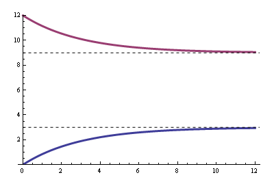
The blue curve is the voltage between A and B, the purple curve is the voltage at B with respect to ground.
