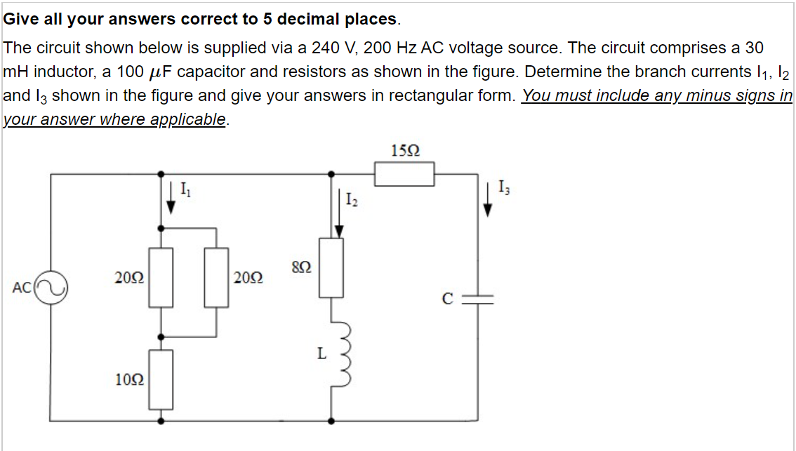
I've added some comments, already. But perhaps the first thing I need to do is to explain why each branch is independent. So before I show you a redrawn schematic, let's talk about ideal voltage sources for a moment.
When you see things wired together, it often means that the components interact with each other. For example, there's a wire connecting an \$8\:\Omega\$ resistor to a \$30\:\text{mH}\$ inductor. And the fact that they are wired together like that is important. You cannot ignore it.
So I get it that when you also see another wire tying together all those branches, that it's all too easy to imagine that there is also some mysterious, complicated stuff going on that wire that you have to figure out and master.
But in the case of ideal voltage sources driving those wires, that concern is no longer true. A car has a battery and it is connected up to a lot of different subsystems in the vehicle. But each subsystem can be designed without knowing about the other subsystems because an ideal voltage source (which the car battery is close enough to) doesn't allow variations of one subsystem to interact with another subsystem.
This fact about voltage sources is one of the saving graces about electronics design. If a designer had to know about every single other subsystem that their module would connect up with, both now and ever into the future, nothing would be able to be done, in practice. Things would be very much more complicated than they really are.
A way to look at this is that suppose your 3rd branch reacted in some way and tried to drive a return signal back into the voltage source wires it is connected to? Well, this signal (or burp or whatever) would "see" your 1st and 2nd branches -- true enough -- but then it would also "see" the voltage source, which has zero impedance. It's a dead short, in effect. (Except that there is a voltage difference across it.) So the signal (or burp) would simply use the path of least resistance and be swallowed up by the voltage source. (Since the path of least resistance here is infinitely smaller than the other branches all of it would be swallowed up by the voltage source with none left for the other two branches.)
A wire tied to a voltage source is better off just being removed. You don't bus around voltage source wires. It just confuses you to do that. Instead, just label, appropriately, instead. And the schematic will be a lot easier to follow.
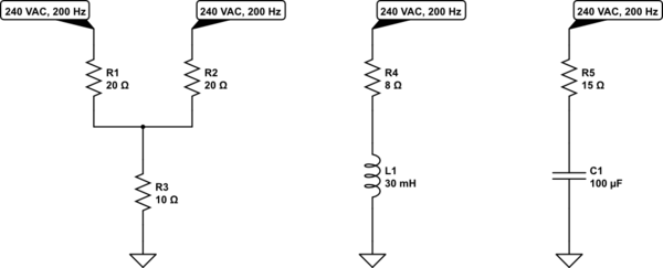
With that out of the way, here's your new equivalent schematic:

simulate this circuit – Schematic created using CircuitLab
I've removed all the busing of power because there's no need to see it. (It's only important to know about when wiring up the circuit with real wire or when the circuit is a practical design where wires are NOT considered to be ideal and where power supplies are also NOT considered to be ideal.)
Now, you can see that you have three completely independent branches. One has nothing to do with any of the others. You can analyze each one independently from the others.
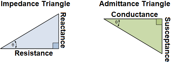
Remember your triangles:
\$\quad\quad\quad\$
The reactance of your inductance is usually treated as positive (which is what the left-hand triangle shows.) But the reactance of your capacitance is usually treated as negative (so the left-hand triangle will have the vertical side going down instead of up, as shown.)
I assume you know how to compute the reactance, X, for both inductors and capacitors.
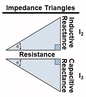
So here's the two triangles you need for the indicated branches:
\$\quad\quad\quad\$
Just note that the resistance leg is different for each triangle. (Should be obvious.) And that the impedance leg is also different as they are computed from entirely different types of components and likely won't work out to the same value, either. Once you draw those out you can get the impedance magnitude from the hypotenuse and divide that into the voltage supply value to compute the current magnitude. You can work out the value of \$\theta\$ in each case, as well, using the arctangent of the opposite side (reactance) divided by the adjacent side (resistance.) One angle will be positive and one will be negative.
So that's it.


