1
\$\begingroup\$

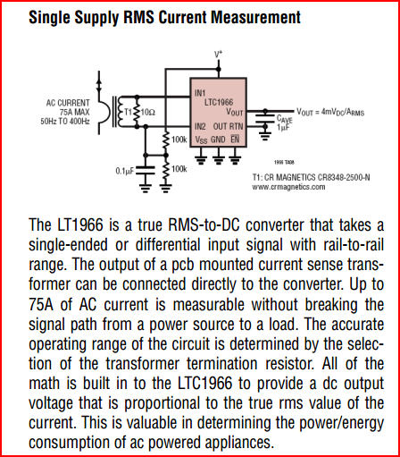
I've the following circuit , that used to measure the current through shunt resistance ,

The circuit have analog & digital ground , the terminals 1 ,2 ,3 are for AC source .

I need to protect this circuit from shorts .

So where's the right place to put the fuse ? & how to know that this is the right place ?

Will be a fuse on the digital side and the analog side ?

any other recommendation for this circuit ? I found out that 7805 voltage regulator is getting hot fast .

Edit #1 :-

R3 is shunt resistor with 200 u ohm resistance
enter image description here

\$\endgroup\$
11
  • 1
    \$\begingroup\$ Possibly helpful question for the '7805 voltage regulator is getting hot fast' problem: electronics.stackexchange.com/questions/18478/… \$\endgroup\$
    – m.Alin
    Commented Jul 8, 2012 at 19:20
  • \$\begingroup\$ What voltage is the AC source? Where is it coming from? \$\endgroup\$
    – Oli Glaser
    Commented Jul 8, 2012 at 20:13
  • \$\begingroup\$ @OliGlaser it's coming from the wall outlet \$\endgroup\$
    – xsari3x
    Commented Jul 8, 2012 at 20:25
  • 2
    \$\begingroup\$ Several people have said it already BUT DO NOT USE THIS CIRCUIT. This circuit can kill you and your connected circuitry. Use an isolated supply. \$\endgroup\$
    – Russell McMahon
    Commented Jul 8, 2012 at 22:08
  • 1
    \$\begingroup\$ Why do you not want to use a "transformer", and what do uou undersytand that word to mean? It could be a metal core mains transformer, or a high frequency switched mode inductor with ferrite or iron powder or air core. | A switch mode solution can be SMALLER than you can make a capacitor based solution with a properly rate capacitor. There are other properly isolated non transformer solutions but they are harder to do and rare (eg piezo-mechanical coupling, light power transfer, acoustic, ...) . A transformer is THE best solution all round. \$\endgroup\$
    – Russell McMahon
    Commented Jul 9, 2012 at 0:58

2 Answers 2

3
\$\begingroup\$

I would put the fuse between pin 1 of the terminal block and R3. Directly after pin3 is probably just as good.

I hope R3 is not realy 10k?

And I hop you are aware that the circuit before the 7805 is tricky, and may cause 'interesting' side effects, like a shocking voltage on the terminal block pins after you disconnected the mains? I would expect at least a bleeder resistor over C3 (but maybe I am too pessimistic).

\$\endgroup\$
3
  • \$\begingroup\$ R3 is 200 u OHM (Shunt resistor ) used for measuring , what do you mean by "bleeder " resistor ?? \$\endgroup\$
    – xsari3x
    Commented Jul 8, 2012 at 20:54
  • \$\begingroup\$ Also any suggestions ? \$\endgroup\$
    – xsari3x
    Commented Jul 8, 2012 at 20:55
  • 1
    \$\begingroup\$ A bleeder resistor would discharge the capacitor within a reasonable time after disconnecting the mains. \$\endgroup\$ Commented Jul 9, 2012 at 7:07
2
\$\begingroup\$

It sounds like (from your question and comments) this circuit is absolutely not suitable for what you are trying to do. If you were not aware that this is not isolated, (and you already had a lucky escape by the sounds of it) then I think maybe you should wait a bit until you try and work with mains voltages.

If you are determined to go ahead though, you need to isolate the high voltage parts from your circuit.
Your microcontroller should be driven by an isolated power supply (i.e. with a transformer present) This can be switching or linear - either way I would buy one rather than try to make one.
For the current sensing, a current transformer (CT) or hall sensor would be probably your best options. Both of these can sense the current but isolate the high voltage from your circuit.
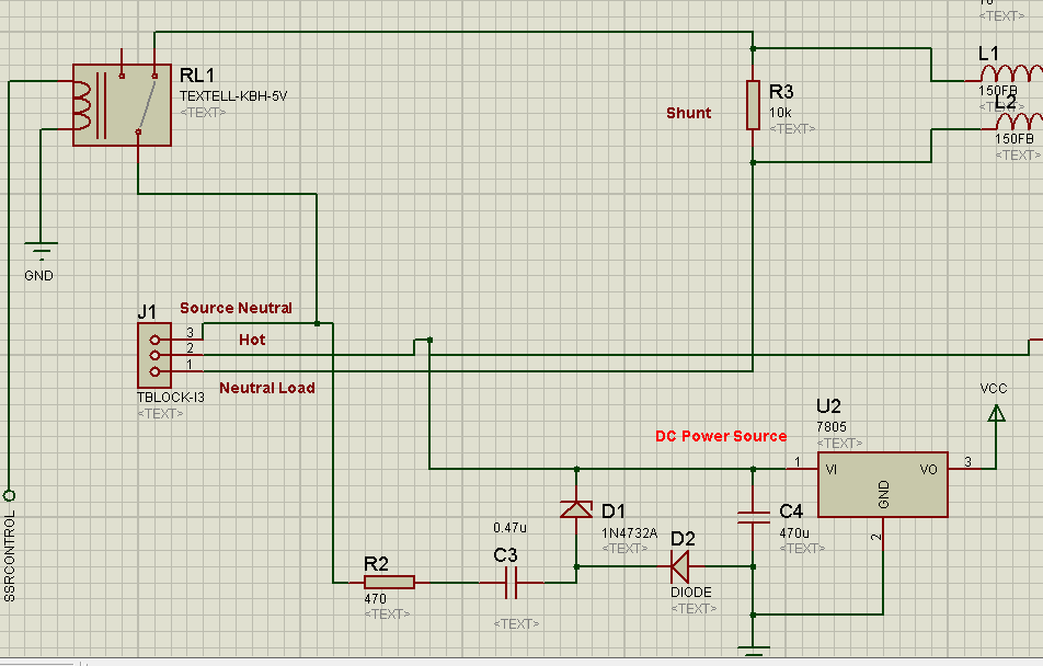
You can buy a CT, then build a simple rectifying circuit and read using your micros ADC, or you can buy dedicated ICs for this purpose:

IC option

\$\endgroup\$
2
  • \$\begingroup\$ I don't have the ability to buy this chip now , it's my graduation project will be delivered in 3 days , do you have another solution for it maybe a simple power supply & attain the necessary isolation \$\endgroup\$
    – xsari3x
    Commented Jul 8, 2012 at 22:12
  • \$\begingroup\$ There are many solutions to your problem since this is a one-off school project. For example, a "wall wart" AC adapter with the appropriate voltage and power rating could be wired into your project chassis. You could pick a regulated one to provide the V_CC directly or an unregulated one to feed U2. \$\endgroup\$ Commented Jul 8, 2012 at 23:25

Your Answer

By clicking “Post Your Answer”, you agree to our terms of service and acknowledge you have read our privacy policy.

Not the answer you're looking for? Browse other questions tagged or ask your own question.