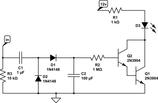
The cheap and convenient hall effect liquid flow sensors available for a few bucks online nearly all cite the device output as being a square pulse train whose frequency is a linear function of the flow rate.
My application is a water flow indicator. No measurement of flow rate, no microprocessors needed - just an output that indicates whether water is flowing or not flowing.
All the devices have a hall sensor and a pinwheel and a conditioning/amplifying/shaping circuit internal to the assembly, but I have not seen anywhere information that says if the output remains high (or low) when flow stops.
If the pinwheel magnet(s) are aligned away from the hall effect sensor when rotation stops then I would expect the output to go to logical 0. But what happens if the wheel stops when the magnet is aligned with the sensor? Does the output now stay high, or is the internal circuitry such that there has to be changing flux for there to be any pulse train at all, and there is a defined state for "zero flow"?
Anyone know from experience before I start breadboarding and prodding the pinwheel?
Thanks
EDIT April 2021. As it happens Jasen hit the nail. The output remains randomly high or low depending on where the pinwheel stops. Pity: would make more sense to have an edge triggered pulse output as Tony Stewart suggested. Random is rarely useful!

