0
\$\begingroup\$

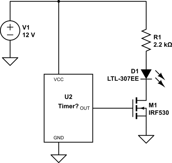
I have a circuit where I have 12VDC source that is connected to the MOSFET (A2SHB) via a timer that applies the voltage to an LED. I have also wired the 12V straight to the LED via a resistor for a constant 8 volts on the LED. The result is that the LED is always on and then the timer comes on and the LED gets brighter making the LED appear to be blinking.

My concern is that with a constant 12V on the drain of the MOSFET, I am causing it to fail because sometimes the LED won't blink until I cycle power.

I am a complete novice at this. I have included a schematic that I think is how I have it wired.

enter image description here

Thanks in advance for any help on this.

\$\endgroup\$
5
  • 1
    \$\begingroup\$ What does the MOEFET datasheet say? Most 20 V continuous 30 V peak MOSFETs will break down the gate structure if you apply over 20 V continuously. It may take hours or weeks. Also your schematic is bogus. You don’t want to short your powersupply with your MOSFET. \$\endgroup\$
    – winny
    Commented Mar 27, 2018 at 15:48
  • \$\begingroup\$ Not sure what should be looking for on the datasheet. Here is a link to it: mikrocontroller.net/attachment/212878/HM2302A.PDF \$\endgroup\$
    – Safant
    Commented Mar 27, 2018 at 15:50
  • 1
    \$\begingroup\$ “constant 8 volts on the LED“ That’s not how LEDs work. You choose your resistor to give a suitable current though the LED. Not voltage over it. \$\endgroup\$
    – winny
    Commented Mar 27, 2018 at 15:55
  • 4
    \$\begingroup\$ The way you've wired it, the LED will remain on until the MOSFET is turned on. At that point, the MOSFET will short out the powersupply, extinguishing the LED. This of course removed the drive to the MOSFET gate and allows the power supply to come back on. If the supply takes an instant to settle, i.e. produces a slightly higher voltage before it's stable, that could account for the higher LED output. As long as the timer switch remains closed, this on-off will continue until the power supply breaks or the MOSFET fails. \$\endgroup\$
    – AlmostDone
    Commented Mar 27, 2018 at 15:59
  • \$\begingroup\$ Ok. Thank you everyone for the input. I am not sure how to put this circuit together without doing harm to the components. I will probably not wire it up this way in the end. I was trying to get a blinking led setup but will just go for a solid color. \$\endgroup\$
    – Safant
    Commented Mar 27, 2018 at 16:08

3 Answers 3

4
\$\begingroup\$

Pretty much everything about this circuit is wrong.

If your schematic is accurate, you are blinking the LED by shorting out your 12V rail. This is NOT a good idea, for a couple reasons:

1) I don't know what your "timer" is, but I doubt it likes having its power supply shorted every time the LED is turned off.

2) Depending on how much current the 12V supply can source, it could easily destroy the MOSFET because the current is too high (nothing to do with the voltage).

3) Depending on what kind of supply the 12V is, shorting it out could damage it or at least trigger an overcurrent reset which will mess with your timing.

Below is an example of a correct way to switch an LED. I'm assuming the "timer" is "some circuit which is powered from 12V and generates a square wave output at suitable levels for the MOSFET gate limits". (As Christ Stratton and other mentioned, 12V gate drive is too high for this MOSFET)

schematic

simulate this circuit – Schematic created using CircuitLab

\$\endgroup\$
1
  • 2
    \$\begingroup\$ Do however note Winny's point that the question's MOSFET cannot tolerate 12v gate drive - so that "suitable gate drive" caution is a real issue, not just a point of academic correctness. \$\endgroup\$ Commented Mar 27, 2018 at 19:05
0
\$\begingroup\$

When the gate voltage is low, there will be no problem having 12 V on the drain, assuming you've chosen a MOSFET rated for more than 12 V.

When the gate voltage is above threshold, this circuit will likely damage either the FET or the 12 V source, because there is nothing to limit the current from the source through the FET when the transistor is "on".

As another answer points out, your FET is not rated for 12 V between gate and source, so if your "TIMER" block connects the full 12 V to the gate, that is another problem.

\$\endgroup\$
0
\$\begingroup\$

Your drain is fine, but you are operating the gate outside of what your MOSFET is rated for unless you magic timer block somehow outputs a lower voltage. Take a look in the datasheet under Absolute max rating and gate-source voltage. +-10 V. enter image description here

For a short bench test, I wouldn’t worry about it but you will most probably break down the gate oxide layer over time and short the MOSFET.

However, your schematic is bogus as the MOSFET shorts out the powersupply. You want your MOSFET in series with your LED+resistor, not parallel to it.

\$\endgroup\$

Your Answer

By clicking “Post Your Answer”, you agree to our terms of service and acknowledge you have read our privacy policy.

Not the answer you're looking for? Browse other questions tagged or ask your own question.