There are special analog optocouplers exactly for such purposes you are decribing.
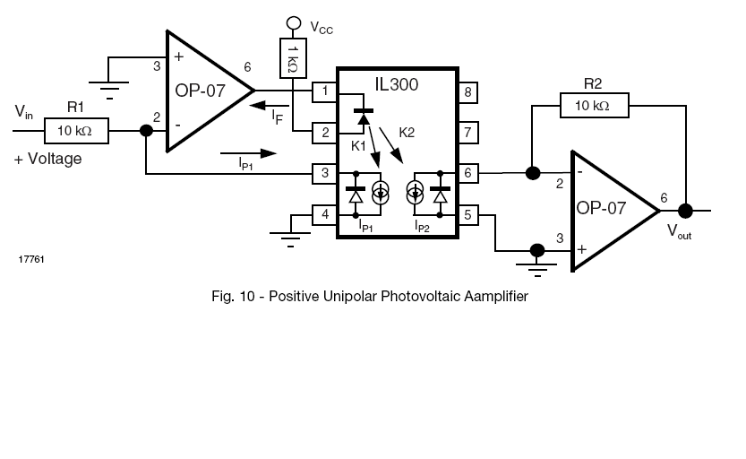
For example see the circuit with an IL300 below.
Such optocouplers have not only one but two photodiodes that are illuminated by the same LED.
The reason for two photodiodes is to use one for a feed-back-loop on the transmitter side that takes care that the photocurrent \$I_{P1}\$ is proportional to the input voltage \$V_{in}\$.
The second photodiode on the receiver side will have a photocurrent \$I_{P2}\$ that is proportional to the first one because it is illuminated by the same LED. The photo current on the receiver side is transformed into a voltage signal \$V_{out}\$ by a TIA.
This way an analog voltage signal can be transfered with high linearity across a galvanic isolation.

There are also other methods, e.g. using a
- voltage to PWM converter or a
- voltage to frequency converter
and
- a common optocoupler or
- a transformer
to transfer the digital signal to the isolated side and convert it back to a voltage signal.

