0
\$\begingroup\$

-I want to have the same potential or linearity in opto isolator's input and output

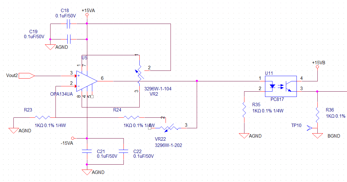
  • Pic below there is my previous circuit ,sketch and Changed Sketch(the last pic),but it's not linear with PC817.

  • I have thought about using HCNR201,TI staff recommend me to use AMC1311,but i don't know how to used it .

  • Hope all kind of advice and suggest or recommand another IC for it

Thanks All First

Pervious PC817 circuit

Previous Sketch

Current Sketch

\$\endgroup\$
5
  • \$\begingroup\$ Follow the App note. ti.com/lit/an/sbaa229/sbaa229.pdf \$\endgroup\$
    – D.A.S.
    Commented Mar 30, 2018 at 7:17
  • \$\begingroup\$ You can also use IL300 \$\endgroup\$
    – D.A.S.
    Commented Mar 30, 2018 at 7:25
  • \$\begingroup\$ What is the upper frequency of interest? What accuracy do you need? \$\endgroup\$ Commented Mar 30, 2018 at 10:49
  • \$\begingroup\$ Look here \$\endgroup\$
    – Curd
    Commented Mar 30, 2018 at 10:51
  • \$\begingroup\$ In case you overlooked cost or BW , a Microchip serial ADC is cheaper with a digital optoisolator \$\endgroup\$
    – D.A.S.
    Commented Mar 30, 2018 at 13:01

1 Answer 1

2
\$\begingroup\$

I want to have the same potential or linearity in opto isolator's input and output

You do not seem to be aware that potential and linearity are not remotely the same thing. And linearity is your problem.

If you go to the data sheet and look at Figure 6, you will see why your circuit does not work the way you want. The CTR is not remotely constant. With non-constant CTR, the current out is not proportional to the current in, so your circuit is wildly non-linear.

If you want to take your chances, get two of the same model and date code, and try replacing your optocoupler with
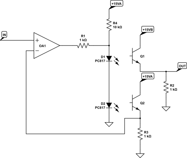
schematic

simulate this circuit – Schematic created using CircuitLab

There is no actual guarantee that the two units will have exactly the same CTR curves, but you can at least give it a try. With the same model numbers, the CTRs should be something close, and you can vary R2 to do a first-order gain matching.

\$\endgroup\$
10
  • \$\begingroup\$ They have dual emitters in 1 package now but with 2 there will always be ESR and efficacy mismatch in emitters upto(+\-50%max) unless same batch \$\endgroup\$
    – D.A.S.
    Commented Mar 30, 2018 at 12:55
  • \$\begingroup\$ @TonyStewart.EEsince'75 - Yeah, which is why I suggested varying R3 as compensation. As long as the slope of CTR vs current is similar, the matching will sort of work. \$\endgroup\$ Commented Mar 30, 2018 at 18:07
  • \$\begingroup\$ if the CTR ranges from 80~600% how well does the slope match? perhaps it only requires a bit of calibration for gain for small changes in effective loss of emitter follower. I would choose Rb/Re=1 using 10k to reduce effect of hFE and limit variation to LED efficacy at low current so ESR variance is minimized, but then you need more current to get more BW \$\endgroup\$
    – D.A.S.
    Commented Mar 30, 2018 at 19:33
  • \$\begingroup\$ Actually, 10k is a good idea due to the peak in the CTR/current peak at about 2-3 mA, which will cause the buffer to latch if you try to go higher. As to slope matching, I have no idea. Certainly LED irradiance and photodiode response slopes are fixed, but I wouldn't want to build a commercial product around my circuit. For somebody who's just learning, though, I thought it would be educational. \$\endgroup\$ Commented Mar 30, 2018 at 21:19
  • 1
    \$\begingroup\$ maybe i'll try to use IL300 to be it more linear \$\endgroup\$
    – 張譯安
    Commented Mar 31, 2018 at 7:42

Your Answer

By clicking “Post Your Answer”, you agree to our terms of service and acknowledge you have read our privacy policy.

Not the answer you're looking for? Browse other questions tagged or ask your own question.