4
\$\begingroup\$

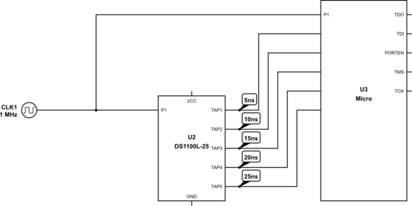
In a circuit I am looking at, a frequency output is fed to a micro-controller for pulse counting and also goes to a DS1100L-25 (Timing Delay Element IC). The output (all five taps) of this IC goes to the micro-controller as well. I am struggling to understand why/how this component would be used and how a delayed signal as well as the original signal help?

The input has a maximum input frequency of 10KHz (not 1MHz). The output from the micro controller is SPI.

schematic

simulate this circuit – Schematic created using CircuitLab

My initial thinking was that it would help with accuracy somehow but I cannot work the mechanism/logic behind this.

TLDR; Why would you need a delayed signal as well as the original for a pulse counter?

\$\endgroup\$
4
  • \$\begingroup\$ Link to the original design please. \$\endgroup\$
    – Andy aka
    Commented Apr 9, 2018 at 11:08
  • \$\begingroup\$ Sorry, I cannot link the original design. There is nothing of interest in the original schematic. It contains two regulators (5vin, 3.3V out and 10V out), EEPROM and lots of decoupling capacitors. \$\endgroup\$
    – R.Joshi
    Commented Apr 9, 2018 at 11:21
  • \$\begingroup\$ Well there might be a part number of the micro, the micro plays an important role and not all are built equal. \$\endgroup\$
    – Arsenal
    Commented Apr 9, 2018 at 11:27
  • \$\begingroup\$ PIC32MX440F256H, 8MHZ Crystal. I am not sure about the operating frequency as I don't have access to the code. \$\endgroup\$
    – R.Joshi
    Commented Apr 9, 2018 at 11:36

2 Answers 2

7
\$\begingroup\$

Clearly, they wanted to get a more accurate estimate of the phase of the input signal transitions relative to the CPU clock, which is presumably on the order of 33-40 MHz (\$\frac{1}{30 \text{ns}}\$ to \$\frac{1}{25 \text{ns}}\$).

GPIO inputs are fed through FFs inside the microcontroller in order to avoid problems with asynchronous sampling and possible metastability. This limits your ability to measure the phase of a transition to the clock period (25 ns). By providing multiple delayed copies of the signal in this manner, you can determine the phase with a resolution of 5 ns by looking at the pattern of bits captured in the FFs.

                        _________________|__________________________
signal  _______________/                 |
                             ____________|__________________________
signal + 5ns  ______________/            |
                                  _______|__________________________
signal + 10ns ___________________/       |
                                       __|__________________________
signal + 15ns ________________________/  |
                                         |  ________________________
signal + 20ns ___________________________|_/
                                         |       _____________________
signal + 25ns ___________________________|______/
                                         |
                                         +---> 111100

For example, if the CPU clock should happen to fall where I've drawn the vertical line, you'll read a pattern of "111100", which tells you that the signal transition occurred between 15 and 20 ns before the clock edge. This gives you the same timing resolution that you'd get with a 200 MHz sample clock, but without requiring a processor that can run that fast.

BTW, the generic term for this kind of encoding is "thermometer code".

If the goal of the system is to measure the frequency or period of the input signal, this approach allows you to achieve a given level of precision in 1/5 the integration time, which could be significant in a production environment.
\$\endgroup\$
-2
\$\begingroup\$

What you show makes very little sense, especially if the instruction period is larger than 25 ns. That would mean that all edges show up in either one instruction or in two consecutive ones. The edges might be used to gate different counters, but then those counters need to be able to handle 200 MHz for the delays to be meaningful.

Maybe this was done for testing how the micro reacts to interrupt conditions during different parts of a cycle.

Just because someone drew up a schematic doesn't mean the circuit was well designed. Move along. There is nothing to see here.

\$\endgroup\$
2
  • \$\begingroup\$ Thank you for your answer. The circuit is used for production system so I am 99% its not just for testing. \$\endgroup\$
    – R.Joshi
    Commented Apr 9, 2018 at 11:39
  • 6
    \$\begingroup\$ Just because you don't instantly see the purpose of a circuit doesn't mean that it's a bad design... \$\endgroup\$
    – Dave Tweed
    Commented Apr 9, 2018 at 13:00

Your Answer

By clicking “Post Your Answer”, you agree to our terms of service and acknowledge you have read our privacy policy.

Not the answer you're looking for? Browse other questions tagged or ask your own question.