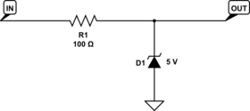
Transmitting 10 Hz over 50 m is not a difficult problem, so you'll find there's numerous ways to do it. For a solution nearly as simple as the one you had before, I'd suggest a simple zener circuit.

Like before, you'd simply supply your sensor with a voltage above 5 V. Say 6 - 12 V, and let this limiting circuit reduce the voltage to a level compatible with your downstream circuit. You'll need to adjust the value of R1 depending on the maximum (or desired) output current of your sensor circuit and the sensor voltage you choose. Cost can be very close to the 7805 solution, depending which zener you choose.
Like the optocoupler suggested in another answer, this provides protection against high-voltage transients induced on the cable, as the zener diodes can shunt these transients to ground. The optocoupler circuit can break ground loops between the sending and receiving systems, but if your 7805 solution is working the zener should work just as well.
Edit
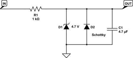
If you're willing to do a little more work, you can improve this circuit by making it slightly more elaborate:

The added schottky diode protects your downstream circuit from negative transients. The zener would have done this, but would have only limitted transients to -0.7 V or so. The schottky will limit them to -0.3 or -0.2 V, which will be much safer for the downstream device if it's a typical logic gate.
The added 4.7 uF capacitor will help to reduce noise when the input is low.
Finally I adjusted the zener voltage down to be sure the output is safe for a 5 V logic gate, even allowing for some drift in the zener voltage, and increased R1 to reduce the current required to drive the input.
All of these things are subject to adjustment to fit the details of your sensor and downstream circuit.
Edit
A key point that I needed to think about overnight before I saw it:
Assuming your 50 m cable contains a signal wire and a ground (or return) wire, an optocoupler protects against common-mode transients (that is, when both the signal and ground wire together change voltage relative to the ground of the receiving circuit), while the zener circuit protects against differential transients where the signal wire voltage changes relative to the ground wire.
If a nearby lightning strike causes the ground and signal wire together to jump to 100 V for a millisecond, you need the optocoupler circuit to protect your receiver from damage.
But if a nearby motor switching on causes the signal wire to jump to 30 V above the ground wire, you need the zener circuit to protect your optocoupler from overload.
Of course, the type of cable and its environment determine which of these scenarios is more likely. If you're using general purpose control wire, either scenario is realistic. If you're using coaxial cable, common mode transients are more likely, but you should also consider the possibility of ESD damage due to handling when the cable isn't attached to the receiver, and also the effect if the cable is initially charged up when it is plugged in to the receiver.


