4
\$\begingroup\$

I have a common anode 4-digit 7-segment display. I have each segment cathode connected to a 330-ohm resistor, and the resistor is connected to a shift register. Each segment cathode is connected to the same shift register. Each common anode is connected to a second shift register. Right now, I am using an Arduino to multiplex the display to show a number.

This works great, but there's a problem. The display isn't bright enough! I assume because this is a common anode configuration, and that the shift register can only provide about 40mA of current for 8 segments (A-G and the decimal point).

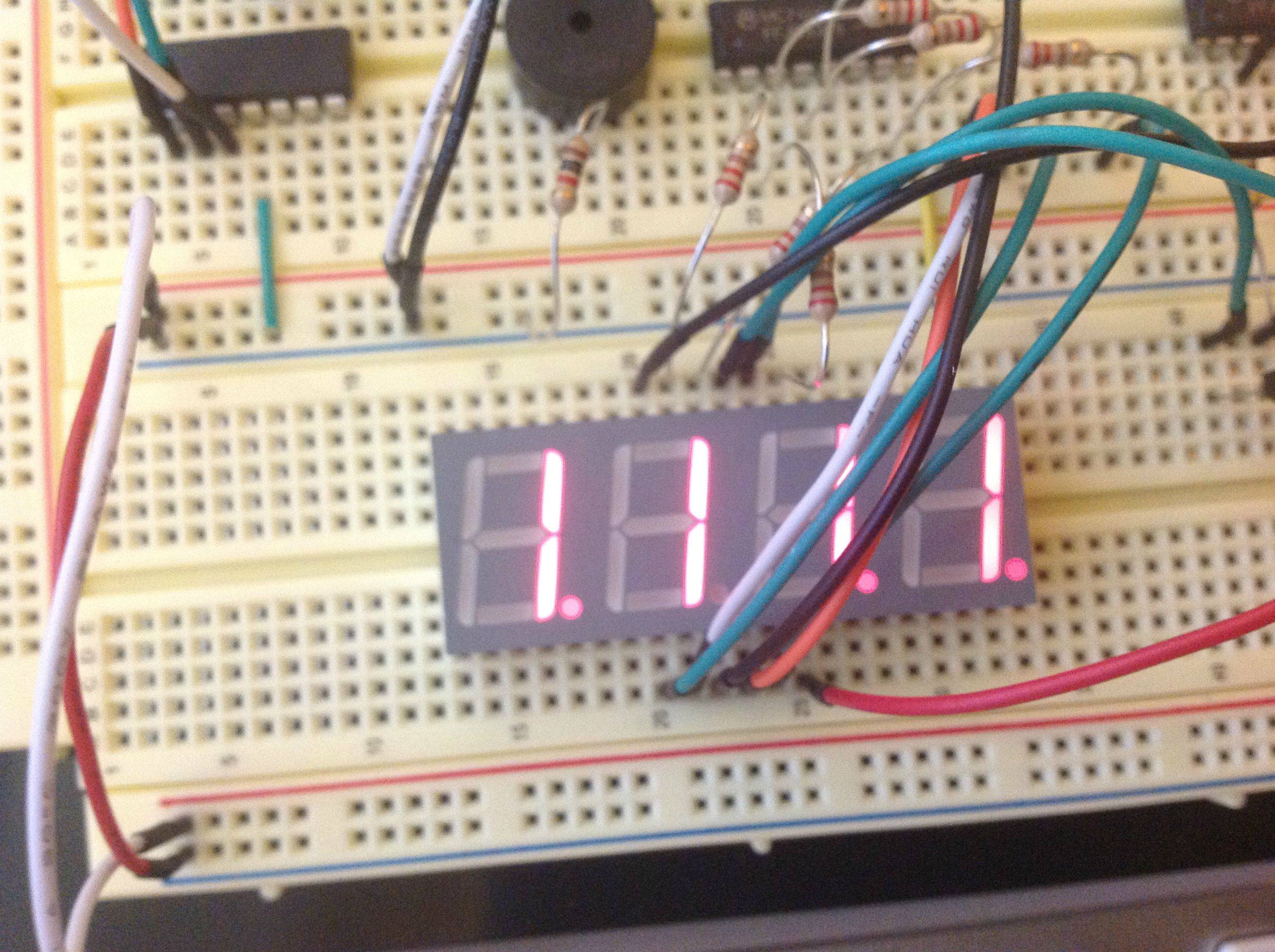
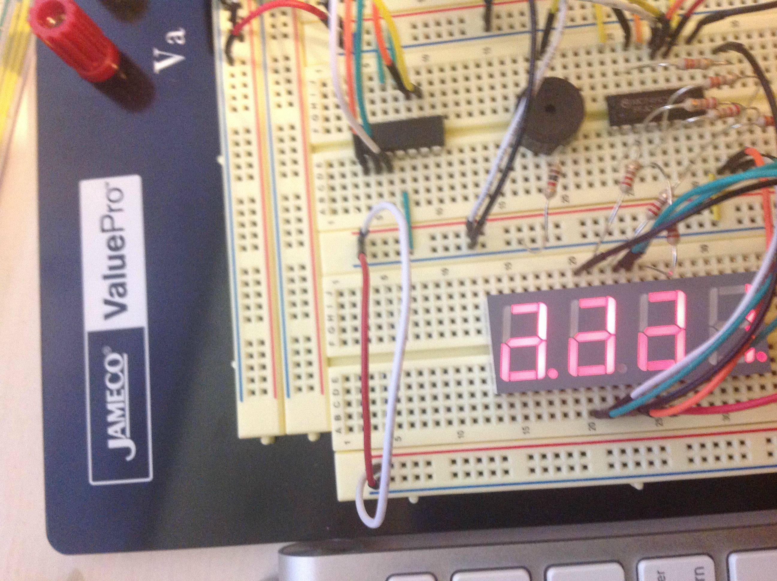
I have decided that I need more power. My first thought was to try to use 4 PNP transistors. I hook them up correctly, and the segments get brighter. Great! However, there is a problem. It seems like the transistor is slowing something down! There is a nasty glow of segments that are used by other digits! I have the microprocessor set to show each segment for 4 milliseconds. The datasheet claims that the transistor should switch on and off faster than that. Why is this faint glow happening?

Here's what it looks like when 1111 is displayed:
enter image description here

Here's what it looks like when 1112 is displayed:
enter image description here

\$\endgroup\$
4
  • 5
    \$\begingroup\$ We really need a schematic of what you are doing to help you efficiently. Can we get a schematic? It might be very easy to resolve. \$\endgroup\$
    – Kortuk
    Commented Jul 29, 2012 at 4:46
  • \$\begingroup\$ Could very well be a software issue too, so code snippets of how you drive output lines (timing) is a good addition too. \$\endgroup\$
    – jippie
    Commented Jul 29, 2012 at 7:21
  • 2
    \$\begingroup\$ I think the code is the likely suspect - my guess is that the problem was "always there", just made more visible with the higher drive from the transistors. Please post the relevant bit of code and a schematic. \$\endgroup\$
    – Oli Glaser
    Commented Jul 29, 2012 at 10:41
  • \$\begingroup\$ 74HC595 has a delay between shifting registers and output registers. \$\endgroup\$
    – user27869
    Commented Aug 23, 2013 at 4:09

5 Answers 5

2
\$\begingroup\$

Here is a possible mechanism for the fault. You say it works (dimly) without the transistors, but doesn't work with them. So it sounds like the fault is in the transistors. Is there some reason that the transistors might be letting some current through when they shouldn't?

Yes. You're using a PNP transistor. As you know, these transistors are on when the base voltage is lower than the emitter voltage. They are off when the base voltage is higher than or equal to the emitter voltage.

The problem with the shift register chip is that the outputs are always lower than the emitter voltage. I couldn't quite make out the part number of the chip you're using, but according to the datasheet for the 74HC595 (page 6), the outputs don't quite reach Vcc. If there is a tiny voltage difference, then you could find that a small amount of current is leaking out of the base of the PNP transistor. With a gain of about 100, you could find that there's enough CE current to give noticeable light output on the LEDs.

Something to try: Add a schottky diode between Vcc and the emitter. This should drop the collector voltage by a fraction of a volt, just enough to allow the shift register to fully turn off the transistor.

\$\endgroup\$
5
  • \$\begingroup\$ Ohhh so I just figured out that I haven't changed my code. I didn't realize that the transistor turns on when the base voltage is 0v. I was basically turning 3 digits' transistors on while turning one off. It was just a code fix. Fail on my part. \$\endgroup\$
    – blake305
    Commented Jul 29, 2012 at 17:17
  • \$\begingroup\$ @blake305 - Ah! I was even going to suggest that very thing, but forgot. Well done. \$\endgroup\$ Commented Jul 29, 2012 at 19:46
  • 1
    \$\begingroup\$ @blake305: any reason why you accepted this answer? With all due respect to Rocketmagnet, but it does not point to the solution. None of the answers does. \$\endgroup\$ Commented Jul 30, 2012 at 6:07
  • 1
    \$\begingroup\$ @FedericoRusso - I was wondering the same. My guess was that this answer pointed to the transistors, and this was the clue that led him to the real problem. \$\endgroup\$ Commented Jul 30, 2012 at 6:57
  • 1
    \$\begingroup\$ @blake305 - If you found the solution you may post it as an answer, which you'll be able to accept in a couple of days. May be useful for others. Don't worry about Rocketmagnet, he'll post another great answer to another question were he can get the accept he would lose here ;-) \$\endgroup\$
    – stevenvh
    Commented Jul 30, 2012 at 7:20
6
\$\begingroup\$

Do not upvote this answer! Blake found the solution himself, but doesn't seem keen on posting it as an answer. I'm just posting as a Wise Lesson for Future Generations.

Driving the common anodes directly he made one output high at a time, and the outputs for the not selected displays low. But adding the PNP transistors inverses the logic, and then you want the selected display output low, and the others high.

So what happens if you forget to invert the anode drivers? Say you want to display "1234". You make the first digit's anode high, the others low, and you output the bit pattern for a "1". Instead of the first digit showing the "1" it remains blank, and the others will show the "1". Move to the next digit. Again, that digit will remain blank and the other three will display the "2". And so on. Due to the multiplexing each digit will display a mix of the other three digits, but not the actual value for that digit.

enter image description here

Blake says this was supposed to be "1112". The first three digits show the mix of "1"s and "2", while the last one just shows the "1" because that's what all the other digits are.

\$\endgroup\$
2
\$\begingroup\$

Rocketmagnet may well be on the right track: the PNPs may have some base current due to leakage by their drivers. If PNP's power supply (the emitter voltage of the transistors) is the same as the HCMOS drivers (HC595?), then this shouldn't be a problem, HCMOS outputs usually stay well within a 100 mV or so of the rails.

If the PNPs' supply is higher then you shouldn't drive them with a push-pull output, but with an open drain/open collector. In that case the leakage current of the transistor when "off" will pass through the PNP's base, and thus amplified. A 2N2907 doesn't have a very high hFE, but it may cause enough collector current to show as slightly uplighting LEDs.

The remedy is simple: add a resistor between the base and emitter of the PNPs. Then as long as the leakage current causes a voltage drop smaller than 0.6 V across the resistor all of it will pass through the resistor, and none through the base. Pick for instance a 4.7 kΩ resistor. Then you'll need at least 130 µA to get the first current through the base, until then all will pass through the resistor. 130 µA is a safe value: it's much larger than the expected leakage current, but much smaller than what the driver can sink.

\$\endgroup\$
4
  • \$\begingroup\$ If the 4.7 kOhm resistor is a pull-up from base to emitter, doesn't its value have to depend on the PNP's power supply (emitter voltage) voltage? \$\endgroup\$
    – m.Alin
    Commented Jul 29, 2012 at 15:26
  • \$\begingroup\$ @m.Alin - No. The emitter is at Vcc, let's say +5 V. The base is 600 mV lower, at 4.4 V. Then the resistor needs 130 \$\mu\$A to get at the 600 mV, and at that time the transistor will begin to conduct. If Vcc would be +10 V then the base will still be 600 mV lower, at 9.4 V. The required voltage across the resistor remains the same. (Maybe you're confusing with an NPN. The PNP is a mirror image of the NPN. So for the NPN current flows from collector to emitter (ground), for the PNP from emitter (+Vcc) to collector.) \$\endgroup\$
    – stevenvh
    Commented Jul 29, 2012 at 15:32
  • \$\begingroup\$ I know the differences between the NPNs and the PNPs. Maybe the leakage current confuses me. What's the path of the leakage current? \$\endgroup\$
    – m.Alin
    Commented Jul 29, 2012 at 16:39
  • 1
    \$\begingroup\$ @m.Alin - Vcc -> PNP's emitter -> PNP's base -> base resistor (I hope he didn't forget that one) -> driver's output (NMOS drain) -> ground. \$\endgroup\$
    – stevenvh
    Commented Jul 29, 2012 at 16:45
0
\$\begingroup\$

It is a very common problem when you are new to multiplexing. Multiplexing means driving one by one LED display. This problem arises when there is still data on output port & you make other display on. DO this - Put data on display port - make any one display on - Put off all data - make display off - very small delay - ......Repeat this step... Your problem will be solved.

\$\endgroup\$
0
\$\begingroup\$

Let's assume a maximum peak current of 20 mA per segment. The low- and high side dirivers will each drop ~ 0.5 V, the display itself will dop ~ 1.5V. Hence the resistor will drop 2.5, so for 20mA it must be 125 Ohm. 120 Ohm will do.

A common shift register will have no problem with 20 mA, but 8 x 20 mA (all segments of one digit turned on) is probably too much. If you have 4 outputs to spare you could use PNP transistors (1k base resistor). Otherwise attach the transistors to your second shift register.

You must realise that you are doing time-multiplexing: you must divide the 'on' time evenly between the 4 digits, and the 'on' time must be much larger than the time required to switch between the digits. This would ask for a low switching frequency, but you don't want to see the switching either, so ~ 100 Hz (2.5 ms for each digit) might be a good compromise.

Your pictures show ghosting: an unwanted digit appears (dimly) superimposed on the digit that should be visible. This is likely caused by swiching the rows or the columns too early. When you can't switch everything in one step (note that you can do that with a cascaded shift register with separate hold register!) you must

  • disable all digits
  • activate the segments for the next digit
  • activate the next digit

Omitting the first step will give you the ghosting effect.

\$\endgroup\$
5
  • 1
    \$\begingroup\$ That's what I would have thought too, but the effect is extreme. Doesn't look like something you can solve by switching the previous display off a few microseconds earlier. \$\endgroup\$
    – stevenvh
    Commented Jul 29, 2012 at 8:01
  • \$\begingroup\$ That depends on how he structured his code. One of my PIC assembler assignments used to be exactly this multiplexing, and I have seen it happening. \$\endgroup\$ Commented Jul 29, 2012 at 8:23
  • 1
    \$\begingroup\$ Also that the ghosting appears two digits further? \$\endgroup\$
    – stevenvh
    Commented Jul 29, 2012 at 10:11
  • \$\begingroup\$ I'm a little puzzled too, would like to see the code/schematic for this. \$\endgroup\$
    – Oli Glaser
    Commented Jul 29, 2012 at 10:38
  • \$\begingroup\$ From the pictures I can't make out which SRs are used. I hope they have output registers... \$\endgroup\$ Commented Jul 29, 2012 at 10:44

Your Answer

By clicking “Post Your Answer”, you agree to our terms of service and acknowledge you have read our privacy policy.

Not the answer you're looking for? Browse other questions tagged or ask your own question.