0
\$\begingroup\$

I am trying to save the context of a microcontroller during a power loss. I already have a detection circuit which tells the microcontroller about the power loss. During a power failure, I needed some additional time for the microcontroller to perform the save operation, hence I have added a large capacitor (1000uF). Everything was working fine with this approach and I was getting more than the required time to complete my operations. Now I needed to connect some other load to the same power supply (some relays) and this reduced the capacitor's discharge rate. As a solution I added a schottky diode (SOD-123) in my circuit before the capacitor and after the relay such that the capacitor charge wont flow back to the relays. Schematic shown below.
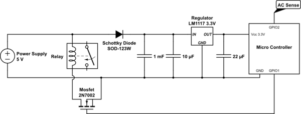
schematic

simulate this circuit – Schematic created using CircuitLab

However I don't see much improvement in the time. My setup works fine when the relays are turned off / removed. Is my schottky rating incorrect? or do I have a better or easy way to handle this ? I won't be able to change my power supply or add too many components due to size constraints.

Note - My brownout voltage is 2.1V and blackout voltage is 1.67V. The Mosfet controls the relay and the relay also has flyback diode (not shown in diagram)

\$\endgroup\$
2
  • \$\begingroup\$ What is the reverse leakage current of your shottkey diode? \$\endgroup\$
    – Colin
    Commented May 10, 2018 at 10:28
  • 4
    \$\begingroup\$ My guess is that the power supply has a large internal capacitor which was working in parallel with your 1mF but now no longer. \$\endgroup\$
    – Oldfart
    Commented May 10, 2018 at 10:41

2 Answers 2

1
\$\begingroup\$

You are reducing the voltage available for the semi-LDO LM1117 before you even get started, so the hold-up time will be reduced significantly. You could use a better regulator and gain that back (and then some), but parts cost will be increased.

Also, particularly at high temperatures (which you may not have yet tested for) Schottky diodes are leaky. There is a trade-off between forward voltage drop and leakage current.

Perhaps you should also check the diode It's possible the startup surge from charging the 1000uF has caused it to go shorted. You don't have any current limiting at all in the circuit, and if you apply a stiff 5V source the diode will see a pretty high surge current. And as @oldfart quite reasonably comments, if there are other hidden parts to the circuit such as a 5V capacitor that you are not showing, there is no way we will be able to figure out what is going on. Please consider my final paragraph though, which applies in any case.

Umm.. why don't you just turn the relay off via the microcontroller, before the 'save' operation commences? You may want to add a pull-down resistor on the gate so if the GPIO goes high-Z the MOSFET is guaranteed to turn off.

\$\endgroup\$
1
  • 1
    \$\begingroup\$ Excellent. I was able to solve it just by turning off the relay before save. Now I get more than a second to do the save operation during a power loss. I hope I can safely remove the schottky diode from my circuit and rely on this. \$\endgroup\$
    – Zac
    Commented May 10, 2018 at 11:08
0
\$\begingroup\$

The dropout in the diode has drastically lowered the already low margin there is before the regulator goes out of regulation. It is rated for 1.1V typical dropout at 100mA, and if the 5V is at -5% that leaves 4.75-1.1-3.3 = 0.35V for the combination of the dropout in the diode and the discharge of the capacitor. That's unrealistically low: the dropout in the diode (like 0.3V @100mA for a good Schottky diode in SOD123W) eats it all!

With C = 1mF and V of discharge to go between the advance warning and the regulator going out of regulation and the microprocessor's operation stops, or worse it become unpredictable, given that t = C*V/I, at I = 100mA, 0.1V of discharge of the capacitor buys a mere 1ms of advance warning (inversely proportional to current consumed). So every fraction of a volt counts!

The easiest could be to use a low-dropout regulator. With a MIC5365-3.3YMT-TZ we go from 1.1V to 0.155V typical @100mA (from 1.2V to 0.3V max), that's like 0.9V saved and probably increases the advance warning afforded by the 1mF capacitor by a large factor (it is hard to tell by how when we don't know when the microprocessor stops operating or becomes unpredictable).

If the microprocessor+regulator consume 5mA, and we can use 1V of discharge of the capacitor thanks to low dropout in diode and regulator, we have 200ms of advance delay.

It is also entirely possible that most of the power reserve really is in the power supply rather than in the 1mF capacitor; then, removing the load as soon as possible will increase the advance delay, and if that's by enough we can remove the diode and probably 1mF capacitor.

It would be interesting to observe the voltage at the 1mF capacitor and the signal giving advance warning, to see both when the warning comes and how the voltage falls.

The schematic lacks the AC sense circuitry, and even what it monitors, so I initially hypothesized that the AC sense does not monitor AC, but rather DC; that would be at one of four possible points: unregulated DC within the power supply block, 5V, regulator input, or 3.3V, from best to worst. The later must be avoided, regulator input is very suboptimal.

\$\endgroup\$
1
  • \$\begingroup\$ I am sensing AC supply using an optocoupler and as mentioned in my post, the circuit works fine when the relays are turned off. \$\endgroup\$
    – Zac
    Commented May 10, 2018 at 10:46

Your Answer

By clicking “Post Your Answer”, you agree to our terms of service and acknowledge you have read our privacy policy.

Not the answer you're looking for? Browse other questions tagged or ask your own question.