I have a 12V PC cooling fan (Evercool PWR-1225H12B) that will run on a 12V regulated supply. Said supply is on a 12 hour daily timer.
In addition to the timed supply, I want to have a solar panel as a backup supply.
The fan draws about 450mA (personally measured) at 12V, full speed. The panel is only 6V (4.5W), but is enough to spin the fan decently.
I'm considering different ways of managing the two power inputs. I have read that solar panels should not be subjected to reverse current, as they may overheat.
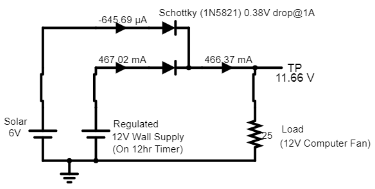
Below is a basic "OR" diode setup. I chose the 1N5821 Schottky because it was rated for 3A and had what I think is a fairly low voltage drop of 0.38V @ 1A. Is that a good choice? When the 12V supply is open, the panel's current is simulated at 227mA. There would be about a 300mV drop across the solar panel's diode, thus about 69mW of wasted energy.
When both supplies are on, the reverse current on the panel is simulated at 645μA, so I think the panel will be fine. Obviously a fan as a load is not just resistor, but because there is a bunch of driving circuitry inside it, I wasn't sure how else to represent it unless I just stick a random inductor in there.
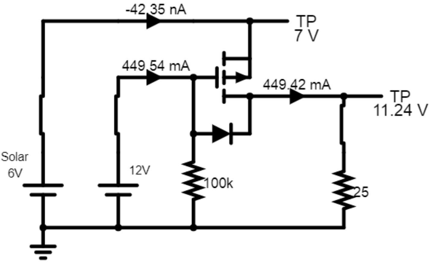
The next circuit is another setup I've seen that uses a PFET. I was thinking that perhaps this would be slightly more efficient for the solar panel, as the FET might have less drop than the diode. This of course depends on which diode and FET I compare. I wasn't sure which PFET to use, so I just entered a beta of 50m and a threshold of -2V. That results in a solar current of 237mA when the 12V supply is open.
Simulations are only so useful. Those above were only using ideal components. I would use ltspice, but I don't have correct SPICE models for the fan or diodes and FETs, so I didn't bother. This is why I'm wondering if anyone has advice on about the pros and cons of different configurations in the real world.


