3
\$\begingroup\$

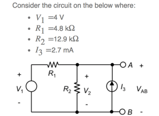
I am working with the circuit shown below.

enter image description here

I am having trouble with the situation where: if a short circuit is connected between Terminals A and B. what current would flow through the short circuit in the direction, A to B?

I am confused about this question. I thought that is would be 2.7 x 10^-3 A (from the current source), however, this is incorrect.

From this circuit, I have also found that the open circuit voltage (VAB) when V1 is acting alone is 2.92V. And that the open circuit voltage when I3 is acting alone is 9.45V. Open circuit voltage when both sources are acting is 12.4V. And finally, I calculated that the Thevenin resistance between A and B is 3.50E+3. (These answers are approximate, as I was asked to give them to 3SF.) I am not sure if these previous calculations help to answering the question that I am confused about.

I would appreciate it a lot if you could please explain this to me.

Thank you very much for you time and help.

\$\endgroup\$
3
  • \$\begingroup\$ You should search on here - a similar question was posted in the last 2 days or so... \$\endgroup\$
    – Solar Mike
    Commented May 20, 2018 at 5:08
  • \$\begingroup\$ I thought that is would be 2.7 x 10^-3 A ... that is 2.7mA .... what else is connected? \$\endgroup\$
    – jsotola
    Commented May 20, 2018 at 5:14
  • \$\begingroup\$ You can't just ignore the voltage source. What if it would be a big 4MW generator generating 100KV. You think that would not influence the circuit? \$\endgroup\$
    – Oldfart
    Commented May 20, 2018 at 5:53

3 Answers 3

1
\$\begingroup\$

Applying a source conversion to the voltage source V1 will make the job easy.
A voltage source V in series with a resistance R can be replaced (Across its two terminals) with a Current source of value V/R with a resistance R in parallel with it.
The proof for this result may be found online in sources such as this.
After performing such a conversion the short circuit current will be the sum of the two sources and independent of R2.

\$\endgroup\$
1
\$\begingroup\$

Hint 1) Installing a short circuit across nodes A and B places a zero-ohm resistance in parallel with resistor R2, which effectively eliminates (removes) R2 from the circuit:

$$ R_{EQ}=R2\,||\,0\,\Omega=\frac{R2\cdot 0\,\Omega}{R2+0\,\Omega}=0\,\Omega $$

So redraw the circuit with the short circuit installed between nodes A and B, and with resistor R2 removed.

Hint 2) After the short circuit is installed between nodes A and B, by inspection we know that the voltage at node 'A' (relative to the reference potential at node 'B') must be zero volts—i.e., \$V_{AB}=0\,V\$. In other words, the voltage across current source I3 is zero volts. (n.b. An ideal current source is a mathematical model, and the voltage across an ideal current source can range from zero volts to infinite volts.)

Hint 3) From Kirchhoff's Current Law (KCL) we know that the sum of all currents entering node 'A' must equal the sum of all currents exiting node 'A'. Or alternatively, the sum of all currents entering and exiting node A must equal zero.

$$ \Sigma(currents\;entering\;A)=\Sigma(currents\;exiting\;A)\\ \Rightarrow \Sigma(currents\;@\;A) = 0 $$

With AB shorted we see by inspection that the voltage at node A is zero volts—i.e., \$V_{AB}=0\,V\$. Therefore, the voltage polarity across resistor R1 is such that a current \$I_{R_1}\$ flows from voltage source V1, through R1, and into node A. You can use Ohm's Law to calculate the value of current \$I_{R_1}\$. The current produced by current source I3 also flows into node A. And according to KCL the the sum of the currents flowing into node A must equal the sum of the currents flowing out of node A, through the short, and into node B, \$\therefore I_{R_1}+I3=I_{AB}\$.

Hint 4) Thevenin Equivalent circuit. In your original circuit with R2 installed and AB open, let current \$I_{R_1}\$ flow from V1, through R1, into node A. Also, let current \$I_{R_2}\$ flow from node A, through R2, into node B. Find \$R_{TH}\$ by opening AB, turning OFF all independent sources (V1=0V, I3=0A), and calculating the equivalent resistance across AB:

$$ R_{TH}=R1\,||\,R2=\frac{R1 \cdot R2}{R1+R2} $$

Find \$V_{TH}\$ by applying nodal analysis (KCL) at node A with AB open:

$$ \Sigma(currents\;entering\;A)=\Sigma(currents\;exiting\;A)\\ \Rightarrow I_{R_1}+I3=I_{R_2}\\ \Rightarrow \frac{V_{R_1}}{R1}+I3=\frac{V_{R_2}}{R2}\\ \Rightarrow \frac{V1-V_{AB}}{R1}+I3=\frac{V_{AB}}{R2} $$

Noting that \$V_{TH}=V_{AB}\$ with AB open, solve for \$V_{AB}\$. After solving for \$R_{TH}\$ and \$V_{TH}\$, place a short across AB and calculate the current through the short, \$I_{AB}=V_{TH}/R_{TH}\$.

\$\endgroup\$
0
\$\begingroup\$

Without the current source, it would be 0.83333mA. With the current source, since it is shorted, there will be no current from it. Thus the current through R1 remains at 0.833 mA.

V=IR, R=0, so the current source damages itself trying to provide infinite current. In reality though, current is monitored by potential difference across a resistor, so current will drop very close to zero and still maintain the required potential difference across the sense resistor.

\$\endgroup\$

Your Answer

By clicking “Post Your Answer”, you agree to our terms of service and acknowledge you have read our privacy policy.

Not the answer you're looking for? Browse other questions tagged or ask your own question.