0
\$\begingroup\$

I want to convert a circuit that runs on 6V DC (from an intermitent power source) to a battery-operated one, by adding a Sealed Lead-Acid (SLA) battery.

This would fulfill the following scenarios:

  1. When intermitent source is active, it powers the system load and recharges the battery;
  2. When intermitent source is shut off, the battery powers the system load;
  3. When intermitent source is active but system load momentarily demants too much power, the battery provides that extra.

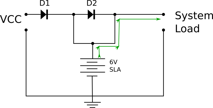
I designed this simple circuit (I am no electrical engineer), and identified a region where I would like the path to be "interrupted" or "switched-off" when VCC is present. The drawings are below.

Nominal VCC is tuned by zener to be 6.8V, suggested by the manufacturer to be a good float voltage to the expected temperature range of use where I live.

So the question is: what components, in what configuration, could be used to "sense" VCC present, and shut the red-circled branch?

I have seen some designs using a mosfet, but I'm not sure where should I put one in this circuit (where to connect gate, drain, source), and if any other component would be needed, and their values.

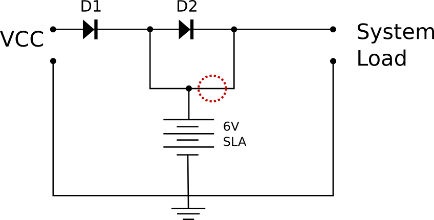
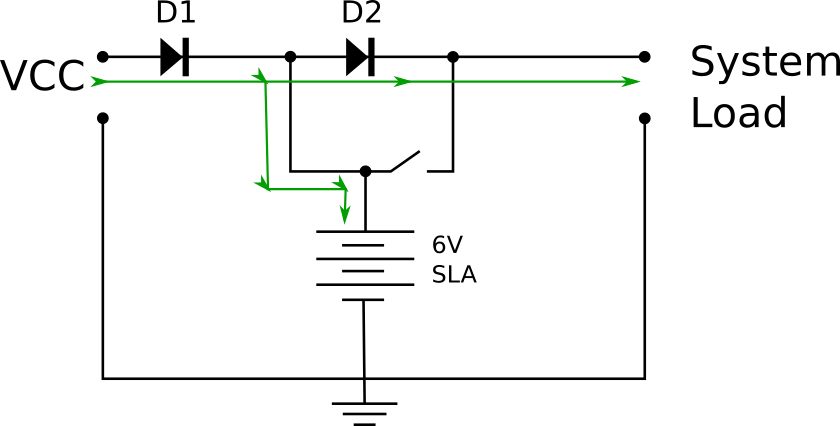
General View:


When external source ON:


When external source OFF:

enter image description here

\$\endgroup\$
2
  • \$\begingroup\$ Is there any reason you don't choose the simple option and just leave out D2 entirely? \$\endgroup\$
    – brhans
    Commented Jun 12, 2018 at 12:33
  • \$\begingroup\$ @brhans Yes: the main reason is that during recharging, VCC is supposed to go above usual battery voltage. My system works best if that variation does not occur (that is, if it is not exposed to the extra voltage). A diode then creates two voltage levels: the system voltage (a little up of 6V), which is provided directly by battery, and the "recharging voltage" (6,8V), which is provided to recharge the battery. What I would like here is to shut off the direct connection between VCC and system load, while dropping it a little with the diode (a Shottky one probably). \$\endgroup\$ Commented Jun 12, 2018 at 12:40

1 Answer 1

1
\$\begingroup\$

I see an issue with your circuit, the charging current of the battery isn't (properly) limited in any way.

As it is now, suppose VCC would supply 6.8 V at very high current, the battery has very little charge and is at 5.5 V for example. Then there would be 1.3 V across D1 and that could be an issue. Too much current could flow potentially causing damage to the VCC supply, the diode and the battery. That's not good.

We EEs generally like to avoid such scenarios so we invent solutions to avoid it. The solution is simple, add a resistor!

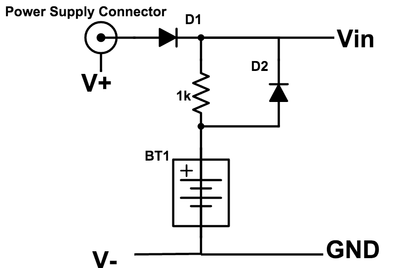
How about this schematic:

enter image description here

I got it from this article which uses 2 AA cells but that doesn't matter. The working principles still apply all the same.

The 1 kohm charging resistor will be too high value for your situation, you will have to recalculate it. You will probably end up with something like 2.2 Ohms or so (just my guess!!). Make sure that the resistor can handle the power it will dissipate at the highest charging current (when the battery voltage is low). For the diodes use a type which can handle the current. Schottky diodes can be a good choice but ordinary diodes will work as well as long as you account for the slightly higher voltage drop.

\$\endgroup\$
4
  • \$\begingroup\$ Thanks for your answer! There are two relevant things in my circuit, that are relevant to this answer: 1) The power source is a bicycle hub generator (properly rectified and regulated), so it has a current limit, being rated at around 500mA, or perhaps a little more than that a higher bicycle speeds. 2) I really would like to avoid putting a diode between the battery and system load. Most my loads are LEDs whose values demand at least 6V to turn on, and their function would be very much affected by the voltage drop from a SLA battery. \$\endgroup\$ Commented Jun 12, 2018 at 13:25
  • \$\begingroup\$ Most my loads are LEDs whose values demand at least 6V Then I would say you have too little margin. If you can accept the LEDs to glow very dimly, use a Schottky diode. Or you could just remove D2 and power the LEDs directly from the battery. If you want the LEDs to always light with the correct brightness I would suggest using a DCDC upconverter to make for example 8 V and drop 2 V using a resistor. Or (more advanced) get an upconverter module with current limiting and operate the LEDs on constant current. \$\endgroup\$ Commented Jun 12, 2018 at 13:33
  • \$\begingroup\$ My choice would be, then, to remove D2. Notice, please, that in my original proposed design, D2 was between Source and Load, while Battery had direct connection with Load, while in this answer it is the opposite (that is, D2 between Battery and Load). Is that intentional? \$\endgroup\$ Commented Jun 12, 2018 at 14:00
  • \$\begingroup\$ It is not only important between which connections the diode sits, its direction is also important. In my schematic D2 bypasses the charging resistor for current flowing from battery to load. In your schematic D2 wasn't doing anything useful in my opinion. Probably in your case only having D1 will be enough (it prevents the battery discharging into the generator) and just connect the load directly across the battery. \$\endgroup\$ Commented Jun 12, 2018 at 14:09

Your Answer

By clicking “Post Your Answer”, you agree to our terms of service and acknowledge you have read our privacy policy.

Not the answer you're looking for? Browse other questions tagged or ask your own question.