0
\$\begingroup\$

I have a USB device with a type A jack connector (see photo). I am integrating this device as a part of another device and due to requirements for ruggedness I would like to have a fully soldered USB wired connection from the CPU module to this device.

As I want to avoid desoldering the type A jack is it possible to just leave it in place and solder my USB cable directly to the USB data/power pins that can be seen on the bottom of PCB?

Will USB 3.0 or at leas 2.0 connection work like this? I wonder whether the bypassed connector will not make any troubles with the USB connection as it is a piece of conductor just left in place.

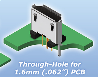
I have one more USB 2.0 device to integrate yet which has a vertical through-hole micro USB connector where I would like to do the same.

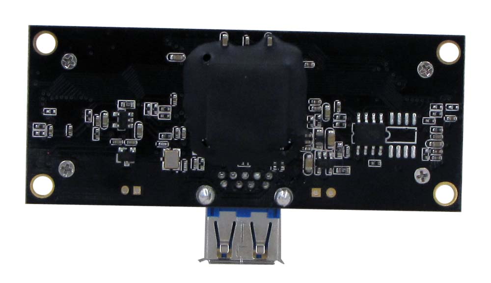
Device #1: enter image description here Device #2:

enter image description here

\$\endgroup\$
5
  • 2
    \$\begingroup\$ Are you sure that soldering wires to exposed pins sticking out of the board will make a more rugged connection than a usb connector? It seems unlikely to me. If you want to make sure it never comes loose, glue it in. \$\endgroup\$
    – Jack B
    Commented Jun 30, 2018 at 17:55
  • \$\begingroup\$ From the design point of view a connector surely is a less reliable form of connection than solder. I think no amount of glue will help here :). Take moisture, rust etc. into account. That is what I will deal with. \$\endgroup\$
    – Kozuch
    Commented Jun 30, 2018 at 18:00
  • \$\begingroup\$ What kind of "CPU module" are you using? How long are the existing traces on that "CPU module", and how are they arranged? BTW, it is illegal for a USB device to use Type-A receptacle, which might be an indication of a shoddy design, and all bets might be off regarding power-on connectivity. \$\endgroup\$ Commented Jun 30, 2018 at 19:02
  • \$\begingroup\$ If moisture is an issue, consider a conformal coat or potting. Either over the connection or better over the whole board. My main worry with solder and ruggedness would be vibration. If you do solder, it would be a good idea to also glue the wire to the board so the solder joint doesn't carry any mechanical loads. \$\endgroup\$
    – Jack B
    Commented Jun 30, 2018 at 20:07
  • \$\begingroup\$ @AliChen: The CPU module will be from FriendlyARM - either NanoPi NEO Air with Allwinner H3 or Smart6818 with Samsung S5P6818. Both fairly small in size. I do not know the design of the boards but they look like common ARM modules. PS. My device #1 if a camera module from Chinese Kayeton which looks like a big manufacturer who should know what it is doing (regarding board design). \$\endgroup\$
    – Kozuch
    Commented Jun 30, 2018 at 20:43

2 Answers 2

2
\$\begingroup\$

I guess you want the link to work at SuperSpeed, although this particular dual-cam fish-eye says something like "USB3.0 High Speed". And the NanoPi NEO Air also seems to be limited to USB 2.0 OTG with micro-USB connector. In any case, if you can find a twinaxial cable, something like this one, and solder the shield properly using 2-3mm-short leads, you should be fine, although some experimentation and measuring eye diagrams may be required.

Twisted pair made of AWG30 Kynar bluewire also works on short distances (1-2"), see this impedance calculator.

If still a problem, your can cut off the connector, body first, then pin-by-pin, but for HS it is unnecessary. Still the use of Type-A receptacle doesn't speak well about the camera manufacturer.

\$\endgroup\$
5
  • \$\begingroup\$ Why it is so difficult to provide direct links to the equipment one wants to integrate and asking questions about it? \$\endgroup\$ Commented Jun 30, 2018 at 21:57
  • \$\begingroup\$ Wow, is that USB-A to USB-A cable on the photos in the link you provided?! Hmm... just did a search "usb 3.0 cable" and got many hits for A-to-A. Looks like manufacturer's answer to that 3.0 abomination of a plug. \$\endgroup\$
    – Maple
    Commented Jun 30, 2018 at 22:30
  • \$\begingroup\$ You got the camera model right. The original question actually tries to abstract from particular HW so I thought the links are not that important. I am less worried about the cable as this post explains the USB cable skew should not be a big problem. As I said I was rather worried about the conductors left in the type A as what I want to do is a non-standard setup. \$\endgroup\$
    – Kozuch
    Commented Jun 30, 2018 at 22:47
  • \$\begingroup\$ @Kozuch, when dealing with non-standard USB connectivity, details are important. USB organisation have made a big effort to provide good signal integrity over connectors and cables, so you can't "abstract" customized hacks. Besides the skew, more important are the differential impedance and shielding (cross-talk or EMI, you pick). \$\endgroup\$ Commented Jun 30, 2018 at 23:07
  • \$\begingroup\$ @Ale..chenski Did you talk about USB 2.0 or 3.0 connection in your answer? I need to make about 2 inch long internal USB 3.0 cable interconnect (connecting 2 PCBs within one device). Will a simple unshielded twisted pair work? At best I would like to use some off the shelf cabling either extracted from regular USB cable, Cat6a/Cat7 etc. or the at worst the twinaxial you suggest. I read about USB 3.0 interference with WiFi etc. I can not imagine how to connect the shield properly - just solder the STP drain wire to connector shield lead on PCB? Would a SATA cable work too? Thanks! \$\endgroup\$
    – Kozuch
    Commented Nov 3, 2018 at 15:07
1
\$\begingroup\$

Although it is not recommended, at USB 2.0 speeds you most likely won't have any problems doing that, interference wise.

What I worry about, though, is the device detection. I saw many times on PC that a plugged in device is not recognized when PC is switched on, until you pull it out and plug back in. This could be specific to USB implementation on PC though.

\$\endgroup\$
2
  • \$\begingroup\$ A connector will not help me with possible device detection issues as the final device will all be enclosed in a case and internals will not be accessible. Were your problems on Windows? My system will run Linux and I hope to be able to solve all possible issues via software. \$\endgroup\$
    – Kozuch
    Commented Jun 30, 2018 at 18:04
  • \$\begingroup\$ Yes, I saw these problems on Windows. Linux USB stack might work just fine, but I recommend testing it thoroughly before making final decision. \$\endgroup\$
    – Maple
    Commented Jun 30, 2018 at 18:49

Your Answer

By clicking “Post Your Answer”, you agree to our terms of service and acknowledge you have read our privacy policy.

Not the answer you're looking for? Browse other questions tagged or ask your own question.