1
\$\begingroup\$

My problem is easy to explain. I want to couple/add some Noise into 240V 50Hz. For this purpose, I have a Noise Generator which is triggered manually with a signal processed by a microcontroller.

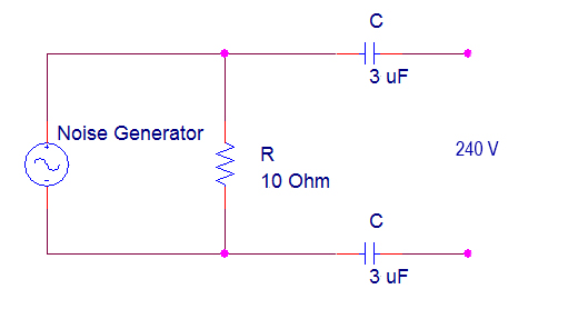
I only have to couple that noise (high frequncy one) into those 240V. I found a PCB which consisted on a high pass filter, so I decided to see if this experiment could work. The idea is using the filter to couple the noise there, and also filtering the high voltage (50 Hz) in order to not to damage the Noise generator. (See the image below). There should be like 40dB of attenuation for the 240V 50Hz, so there is no problem with it I think.

The thing is that this doesn't work, and I dont know why. When I connect the filter, the Noise generator isn't able to get the expected V out, and, as a consequence of this, I dont get the results that I want. I have checked the maximum intensity that this generator is able to deliver (due to the low value of the resistor placed on the filter), and there is no problem with it.

So, is there anything that I am ignoring? Thanks :)

Circuit schematic

\$\endgroup\$
5
  • 1
    \$\begingroup\$ I dont get the results that I want ... this statement contains no useful information ...... it is not possible to help you until you explain what you expect to see and what you actually see \$\endgroup\$
    – jsotola
    Commented Jun 30, 2018 at 22:25
  • \$\begingroup\$ You probably don't take into consideration that your Noise Generator has driver impedance of 50 Ohms. When attempting to drive a low-Ohm load, the signal amplitude could be very low. \$\endgroup\$ Commented Jun 30, 2018 at 22:33
  • \$\begingroup\$ Sorry, my fault The thing it that I want to add some Noise into another point. In this case, this "point" has 240V 50Hz sine wave. When I connect the Noise generator into that filter + 240V, the Noise Generator stops working. It isn't able to work properly. But, when I disconnect it from the filter and see the signal output from the Noise Generator in the osciloscope, it works perfectly. So I dont really know where is the problem or how to make the Noise Generator works with that filter \$\endgroup\$
    – Manu
    Commented Jun 30, 2018 at 22:35
  • \$\begingroup\$ Which filter? Like in your schematics, or what? \$\endgroup\$ Commented Jun 30, 2018 at 22:40
  • 1
    \$\begingroup\$ @Manu: that comment doesn't make it any clearer what you are trying to do. A full schematic would be better than many, many words. Put all the information into the question - not sprinkled through the comments. \$\endgroup\$
    – Transistor
    Commented Jun 30, 2018 at 22:46

2 Answers 2

1
\$\begingroup\$

You are trying to inject noise into the mains supply? (I am wondering - perhaps you want to test some other circuit for immunity to mains born noise? but that's not what you asked, so anyway ... )

There are really good reasons why this probably won't work well, and why you should not try to make it work better. Basically, the mains is a very stiff (i.e. low impedance) source, and you need to use a lot of energy to change it. (Yes, mains born transients are not uncommon but they typical coming from things like high power motors with poor suppression, which do have a lot of energy.) You would need a quite serious power amp after your noise generator.

(Most likely your noise generator is unable to drive the 10 ohm load anyway, unless you are already using a power amp - but don't! - which is another reason this circuit will not work. Whatever energy comes out of your noise source ends up in that resistor, which is low in relation to the 3uF caps, which have an impedance of about 1k each.)

Actually you ought to hope that this doesn't work; basically you are trying to deliberately contaminate the public mains supply, which could have unfortunate effects on other users, and is may well be illegal.

Lastly - you are connecting your "noise generator" (whatever ever it is) to a high voltage source, which might well damage it and also be unsafe.

You probably need to re-evaluate what you are trying to do - and find another way to do it. This sounds quite ill-advised to me.

\$\endgroup\$
1
\$\begingroup\$

it seems like you could try running a LISN in reverse. inject your noise signal into the signal output port, and experience noisy mains on the the power output port.

But if you're actually trying to broadast noise onto all the mains (eg:to thwart powerline communication) it may be much harder.

\$\endgroup\$

Your Answer

By clicking “Post Your Answer”, you agree to our terms of service and acknowledge you have read our privacy policy.

Not the answer you're looking for? Browse other questions tagged or ask your own question.