I have an RF 443.92 MHz transmitter and the receiver, the model is TWS-DS-3 and I'm trying to understand how does it works. There are 4 pins (GND, Data In, Vcc, ANT), I'm going to wire the Vcc on a 5V power (of a Raspberry Pi), the GND on the GND and the Data In on a digital output GPIO that provides 3.3v logic level. What happens when I set the Data In pin to the HIGH state ? It will set the receiver Data Out to the HIGH state too after transmitting ? Do I need any resistor to limit the current between the GPIO data pin or in the Vcc pin ?
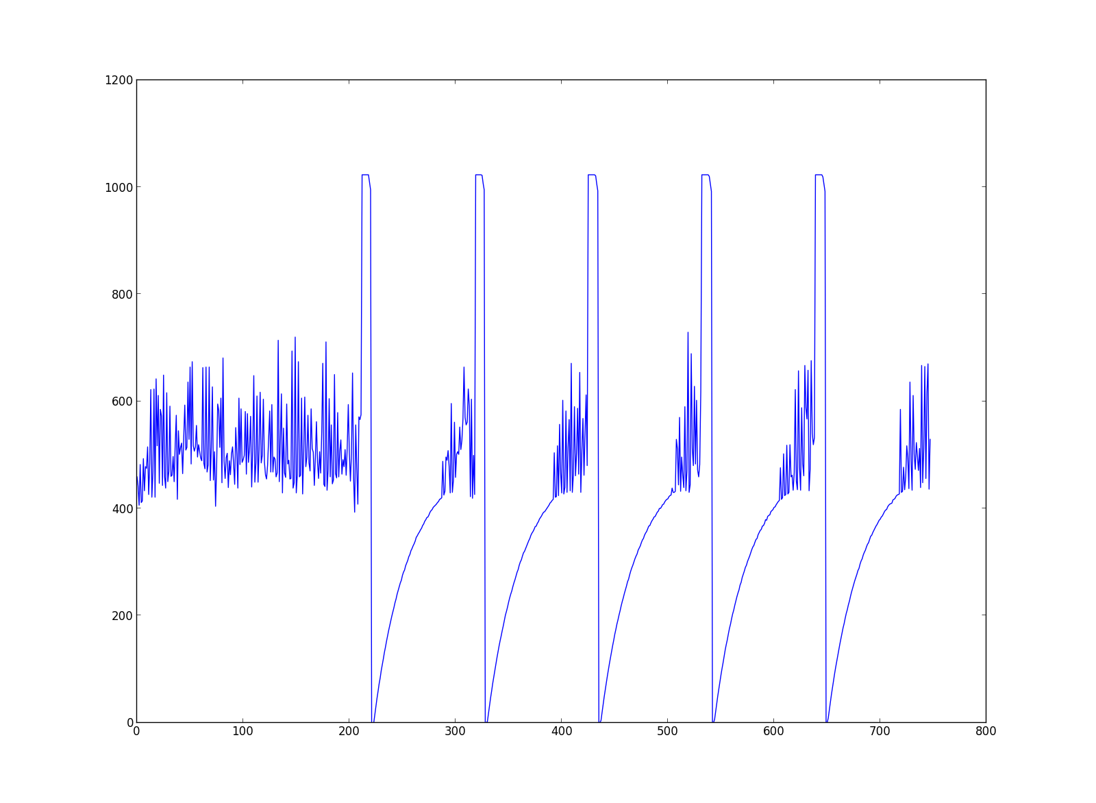
Update: I just plugged the receiver RWS-375-6 into an Arduino with the "Linear Out" pin on an analog pin and the TWS-DS-3 (transmitter) I plugged into a Raspberry Pi, when I set the pin to a HIGH state the output on the analog output of the Arduino is this:

The peaks are when I set the GPIO pin (which is connected into the Data In of the transmitter) to HIGH state, sleep 100ms and then turn it LOW and wait for 1 second.
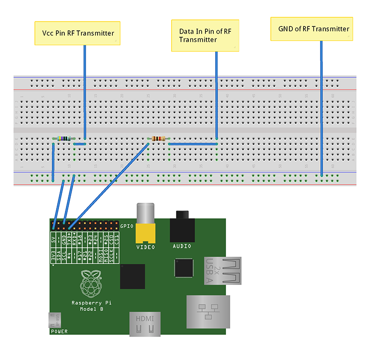
If someone is also interested, here is the wiring I've done on the Raspberry Pi:

