0
\$\begingroup\$

sorry for spamming about questions today, but I am riddled here.

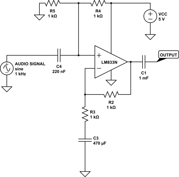
SOMEHOW there's 2.2V at the output is that even possible?!
LM833N Datasheet

schematic

simulate this circuit – Schematic created using CircuitLab

\$\endgroup\$
8
  • 2
    \$\begingroup\$ read about RC time constants and load of 10M DMM \$\endgroup\$
    – D.A.S.
    Commented Jul 6, 2018 at 0:57
  • \$\begingroup\$ What's connected to the output? What's the leakage current spec on the 1mF cap? What happens if you put a 100K pull-down on the output? \$\endgroup\$
    – John D
    Commented Jul 6, 2018 at 0:58
  • \$\begingroup\$ An oscilloscope is only connected to the output, i double checked, but its on the board board with many components on it, maybe that could be it? \$\endgroup\$
    – Leoc
    Commented Jul 6, 2018 at 0:59
  • \$\begingroup\$ @TonyEErocketscientist You were rocket my apologize, adding a load fixed the offset issue. Curious as why this happened? \$\endgroup\$
    – Leoc
    Commented Jul 6, 2018 at 1:02
  • \$\begingroup\$ Caps hold a charge voltage if there is no load. So when power turned on with 0V across cap but it rose to 4V and still 0V across cap \$\endgroup\$
    – D.A.S.
    Commented Jul 6, 2018 at 1:20

1 Answer 1

4
\$\begingroup\$

If it's really 1 mF ( 1000 uF) it's an electrolytic capacitor, which WILL leak ( a few microamps, depending on age, temperature, and bias voltage).

To minimise the leakage it needs to be properly biased (about half its rated voltage) so that the electric field builds up the insulating layer by ... electrolysis. The clue is in its name... If the resulting DC bias is a problem, there are 2 options:

  1. A load resistance of a few kilohms will reduce the DC output to a few millivolts
  2. Or replace the capacitor with a lower leakage type (film cap or ceramic).

See also this Q&A for more details.

Note there is no need for such a large value : you have 0.22 uF into 0.5 kilohms on the input which will severely limit the LF response. 1000 uF would only be appropriate with a load resistance of a few ohms or less, and the LM833 cannot drive such a low load anyway. Your last comment implies it has trouble even driving 100 ohms, which is not very surprising.

\$\endgroup\$
6
  • \$\begingroup\$ When you say the LM833 cannt drive such a low load, is this referred to the VOM? The reasoning I am using such a high value capacitor is due to it high pass nature it creature with the load, the higher I use the likely hood it will pass all the output signal to the output stage. If a lower one would be used it will attenuate the signal at the output. \$\endgroup\$
    – Leoc
    Commented Jul 6, 2018 at 15:35
  • \$\begingroup\$ So what is the load? And what do you mean by VOM? \$\endgroup\$
    – user16324
    Commented Jul 6, 2018 at 15:37
  • \$\begingroup\$ But that makes a lot of more sense, thank you so much for shedding some light. \$\endgroup\$
    – Leoc
    Commented Jul 6, 2018 at 15:39
  • \$\begingroup\$ I have a load currently of 10ohms, it removes the DC offset however the Voltage pkpk severely drops oppose to taking it out. Sorry what I mean is here in the data sheet cause you hinted saying the LM833 cannt drive such a low load, how do you know did you obtain this from the datasheet and so I thought that was referred to the Voltage output swing \$\endgroup\$
    – Leoc
    Commented Jul 6, 2018 at 15:41
  • \$\begingroup\$ Voltage output swing is spec'ed in the datasheet for a load of 10,000 ohms (figs 17,18). Other parameters, for a load of 2 kilohms (Power BW page 3, figs 6,7,8 and others). It will be utterly hopeless driving 10 ohms. Increase the load to 2 kilohms. \$\endgroup\$
    – user16324
    Commented Jul 6, 2018 at 15:45

Your Answer

By clicking “Post Your Answer”, you agree to our terms of service and acknowledge you have read our privacy policy.

Not the answer you're looking for? Browse other questions tagged or ask your own question.