0
\$\begingroup\$

I have a very PCI analog output card which could output a voltage ranged from 0 to 5V. I need a circuit to output a current ranged from 10mA to 90mA. The load is about 45 Ohm.

So is it safe to connect directly the analog output to the load and change the voltage until we get the desire current? Will it burn the card if it is not correctly connected?

I am sorry that I don't have much experience in circuit building. But I read other article about using op-amp to control the output current by input voltage.
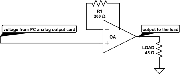
schematic

simulate this circuit – Schematic created using CircuitLab

I wonder if the above schematic is a correct setup to apply a current to a load? What's the advantage to the op amp for this purpose?

\$\endgroup\$
1
  • 1
    \$\begingroup\$ The two answers given seem to be missing the point that the circuit in your question makes no sense and that you appear to require a constant current output rather than some buffer. \$\endgroup\$
    – Andy aka
    Commented Sep 1, 2015 at 7:20

3 Answers 3

1
\$\begingroup\$

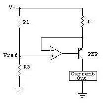
Your circuit makes no sense - feedback resistor connected to some point half way along the op-amp is the problem but, even if it were connected to the output this would be a voltage buffer. If you want a ground referenced current source consider this: -

enter image description here

The voltage across R1 dictates the current thru the load (shown as a box with "current out" written in the middle. However, it is a little inconvenient to have current out controlled by the voltage across R1 and so people tend to make a positive rails referenced current source that feeds R1, then your input voltage (ground referenced) controls a ground referenced load with respect to current.

enter image description here

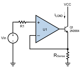
The circuit directly above controls a current from a ground referenced control voltage. Where it says Iload, this feds into R1 in the upper circuit and R3 is discarded.

There are plenty of different ideas for current sources as can be found here.

\$\endgroup\$
8
  • \$\begingroup\$ Hi Andy, thanks for the reply. I read the reference book for electronic. I understand the first case to use Vin to control the output current. But for the second one, what's Rsense? I just have a quick question, someone call it buffer, so does it mean if for reason the load drag too much current, it will burn the opamp but not my card? \$\endgroup\$ Commented Sep 1, 2015 at 12:16
  • \$\begingroup\$ In the 2nd circuit Rsense is chosen to a convenient value because Iload = Vin/Rsense. I don't understand the last part of your comment beginning.... I just have etc.. \$\endgroup\$
    – Andy aka
    Commented Sep 1, 2015 at 12:46
  • \$\begingroup\$ By the way, what model for op-amp should be used to create something with current up to 100mA or more? I am not sure what's the role for the transistor, any instruction to pick the right one? Thanks again. \$\endgroup\$ Commented Sep 1, 2015 at 12:52
  • \$\begingroup\$ I know nothing about your power rails or the required speed of your signal so I can't recommend anything. Apart from the fact that questions seeking recommendations for components are frowned upon because answers like this become quickly out of date. The transistor is fundamental and it will handle the 100mA. \$\endgroup\$
    – Andy aka
    Commented Sep 1, 2015 at 12:56
  • \$\begingroup\$ Sorry for the confusion, what I mean for the second part of my comment is as follows. If says for some reason the load is broken so the resistance becomes zero, it may cause too much current flow on the load. But that current is not generated from the card but from the transistor so the output current from op-amp is still low though the current on the load is high, it will protect the card in this case, is that right? \$\endgroup\$ Commented Sep 1, 2015 at 12:57
1
\$\begingroup\$

Your schematic shows a "buffer" circuit, the opamp just copies the input voltage at it's + input to the output, provided it can drive the output to this voltage and provided the output is loaded such that it can deliver the current.

If you would not use such a "buffer" circuit, all the current to the load would have to come from the analog PCI card in the PC. These are usually not designed to deliver much current, 10 mA will usually be problematic already. So you need something to fix that, this is called a buffer.

You do not need the 200 ohms R1 resistor, you can connect the - input directly to the output of the opamp.

You say you want to control the current but actually this circuit controls the voltage ! Now if the load is constant, for example 45 ohms then this makes no difference as I = V / R. If this is OK for you, meaning that the load will always be 45 ohms, then this circuit is fine.

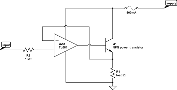
BUT 90 mA will be too much for many opamps, however there are some power opamps that can handle this you will have to look at the opamp's datasheet. You can also let the opamp control a small power transistor so that the power transistor does all the hard work. That would look like:

schematic

simulate this circuit – Schematic created using CircuitLab

\$\endgroup\$
2
  • \$\begingroup\$ Thanks for the reply. In this circuit if says the load is short, will it cause too much current to op-omp? But since we isolate the input with op-omp, even load current is high, it will only burn opamp and/or transistor but not the input electronic, right? \$\endgroup\$ Commented Sep 1, 2015 at 13:09
  • \$\begingroup\$ Correct, this circuit is not designed to handle a shorted output. Indeed the NPN transistor and/or opamp might be damaged in case of a short circuit. The circuits on the PCI card should be safe. T make it even safer, place a 1 kohm resistor in series with the + input. The easiest way to protect against a short is to put a fuse inseries with the supply. A fuse of 500 mA should do the job. See updated schematic. \$\endgroup\$ Commented Sep 1, 2015 at 13:20
0
\$\begingroup\$

Technically speaking your circuit is fine. You've build what is essentially a voltage follower, i.e. a unity gain amplifier. I don;t know why you have a 200E resistance in the feedback; using a wire would work the same. Your PCI card sees a very high impedance and does not source a lot of current. The op-amp will source the current to the load, and the voltage across the 45E Load will equal the PCI card output.

In reality, you need to take care of: 1. Isolating the power supply of the op-amp from the PC power supply, at a minimum. 2. Look at input impedance of the op-amp, output impedance of your PCI card and see how they match up.

\$\endgroup\$
1
  • \$\begingroup\$ thanks a lot. So by 2, do you mean I am building something with op-amp so I can have high impedance also, which will protect my card while it can provide some current controlled by voltage, which is output from the card? \$\endgroup\$ Commented Sep 1, 2015 at 12:17

Your Answer

By clicking “Post Your Answer”, you agree to our terms of service and acknowledge you have read our privacy policy.

Not the answer you're looking for? Browse other questions tagged or ask your own question.