0
\$\begingroup\$

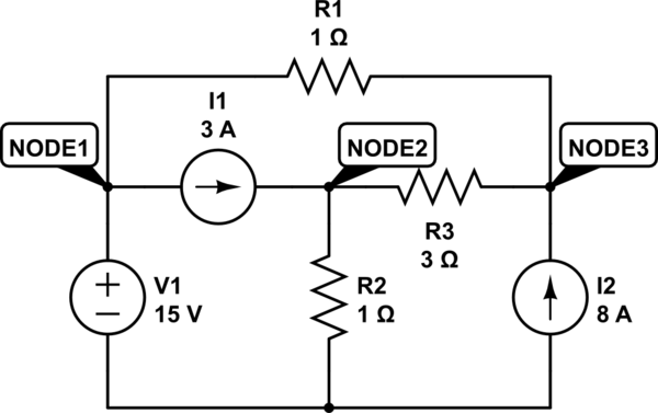
Here is the circuit.
schematic

simulate this circuit – Schematic created using CircuitLab

What do I have to do when there are two different sources?

Find all the voltages in the resistors.

Supposing every current going out of the nodes, here are the equations:

NODE1) \$V1=-15\$

NODE2) \$V2/R2+(V2-V3)/R3-I1=0\$

NODE3) \$(V3-V1)/R1+(V3-V2)/R3-I2=0\$

  • I don't know if the first equation is right, or if it has to be \$-15+(V1-V3)/R1+I1=0\$
  • I don't know what am I supposed to do with the \$V1\$ in the NODE3 equation, using -15 instead of \$V1\$ or simply don't put it. (?)

Considering only the NODE2 and NODE3 equations: \$G*V=I\$ I have to find \$G^-1\$:

\$G^-1=1/detG*(G^a)^T\$

\$G^a\$ = matrix composed by algebraic complements, \$G^T\$ = transposed.

By doing that I find the wrong results.

I know there are many ways to resolve this problem, but I have to practice the node voltage method.

It may be that I made some algebra or numerical errors, I'm trying again in the meantime.

\$\endgroup\$
7
  • \$\begingroup\$ Actually V1 is +15. But in any case your three unknowns are actually V2, V3, and I[V1]. I would write equation 1 as I1-Iv1+(15-V3)/R1 = 0. \$\endgroup\$
    – MikeP
    Commented Jul 9, 2018 at 14:17
  • \$\begingroup\$ @MikeP You could create a new unknown, I(V1), but that is not necessary. The node voltage method produces equations that have the node voltages as the unknown values, even if some of the equations turn out to be trivial. \$\endgroup\$ Commented Jul 9, 2018 at 14:20
  • \$\begingroup\$ Current direction and voltage =0V node are arbitrary, but here the Common Node should be 0V as a reference so that the numbered nodes are consistent, Never include the value and the constant (e.g. V1) both in the same equation. \$\endgroup\$
    – D.A.S.
    Commented Jul 9, 2018 at 14:21
  • \$\begingroup\$ This is almost a duplicate of the question you asked a few days ago: electronics.stackexchange.com/questions/383322/… \$\endgroup\$ Commented Jul 9, 2018 at 14:22
  • \$\begingroup\$ Elliot, the circuit is the same but the question is not similar at all. \$\endgroup\$ Commented Jul 9, 2018 at 14:26

2 Answers 2

2
\$\begingroup\$

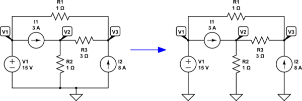
I've added a ground reference to your schematic on the left and then redrew it, on the right:

schematic

simulate this circuit – Schematic created using CircuitLab

You already know \$V_1=+15\:\text{V}\$. That's "free." At this point, you need only quickly write out the other two equations:

$$\begin{align*} \frac{V_2}{R_2}+\frac{V_2}{R_3}&=I_1+\frac{V_3}{R_3}\\\\ \frac{V_3}{R_1}+\frac{V_3}{R_3}&=I_2+\frac{V_1}{R_1}+\frac{V_2}{R_3} \end{align*}$$

I divide up my equations (shown above) using a "mental model" I acquired from reading Spice source code: I place out-flowing currents on the left and in-flowing currents on the right. A current source is either an out-flowing current or else it is an in-flowing current. So I place that on whichever side it belongs, depending on which way it points.

You can re-arrange the above equations per the standard format for matrix solution, if you want.

$$\left[{\begin{array}{cc}\frac{1}{R_2}+\frac{1}{R_3}&\frac{-1}{R_3}\\\frac{-1}{R_3}&\frac{1}{R_2}+\frac{1}{R_3}\end{array}}\right]\left[{\begin{array}{cc}V_2\vphantom{\frac{V_1}{R_3}}\\V_3\vphantom{\frac{1}{R_3}}\end{array}}\right]=\left[{\begin{array}{cc}I_1\vphantom{\frac{V_1}{R_3}}\\I_2+\frac{V_1}{R_1}\vphantom{\frac{1}{R_3}}\end{array}}\right]$$

Now use Cramer's rule, if by hand. Or use Sage/sympy or some other software product, if you prefer. Regardless, the simultaneous solution of the above will produce \$V_2\$ and \$V_3\$ for you.

\$\endgroup\$
2
  • \$\begingroup\$ I resolved it by hand with the 2 eq. system. I made a small math mistake but before finding it I thought I made a mistake during the node voltage method. Thanks a lot for the answer! Up-voted and accepted! :) \$\endgroup\$ Commented Jul 9, 2018 at 23:22
  • \$\begingroup\$ @neilpare Glad to see it's working out for you. Cramer's rule is a handy one to remember when you don't have fancy calculator programs to use at the moment. And hopefully, my "node voltage method" wasn't confusing. I do it a little differently from the "book form" often found. But I like the Spice method better because I make fewer mistakes with signs in the equations that way. \$\endgroup\$
    – jonk
    Commented Jul 9, 2018 at 23:47
2
\$\begingroup\$

When you have a voltage source with one end at ground and you are using the node voltage method you immediately know the voltage at one node by inspection. You do need to be careful with the sign. Look in your textbook or course notes for an example.

When writing node voltage equations you are actually writing a KCL equation. It looks like you are adding all of the current leaving each node and setting the sum equal to zero, which is fine.

We won't solve your homework problems for you so I've just given some hints. You almost have the equations written correctly.

\$\endgroup\$
1
  • \$\begingroup\$ These are not homework, i find these exercises in some university sites. I would not ask for homework since in engineering is pretty much useless if you can't solve something by yourself. Thanks for the hints anyway :) \$\endgroup\$ Commented Jul 9, 2018 at 14:25

Your Answer

By clicking “Post Your Answer”, you agree to our terms of service and acknowledge you have read our privacy policy.

Not the answer you're looking for? Browse other questions tagged or ask your own question.