1
\$\begingroup\$

enter image description here

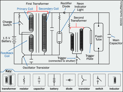
I took apart a "one-way-camera" for the flash part and found a circuit very similar to the image. For a project I need to trigger the flash with a microcontroller (attiny25/45/85v, low voltage version, operates with 1.8-5v). To do that I simply need to bridge the charge switch on turn on and then trigger the flash by replacing the trigger mechanical switch with something else. I am considering several options for this and am hoping on input on what would be the easiest and cheapest option, as I need to produce many of these circuits.

What makes this tricky is that the flash uses more than 1000 volts to trigger and most transistors are not build for that kind of application. Relays have worked fine but especially low coil voltage ones are hard to get/expensive and im wondering if there is a good alternative.

Thank you for your input in advance.

PS: The whole circuit should ideally run on 2 AA batteries (=3v)

\$\endgroup\$
2
  • \$\begingroup\$ Do you need a delayed flash or instant? \$\endgroup\$
    – D.A.S.
    Commented Aug 7, 2018 at 2:04
  • \$\begingroup\$ I want the flash to light up in semi random intervals, so delayed would be fine, however permanetely bridging the trigger does not work in case that is what you were going to suggest \$\endgroup\$
    – WhiteSpin
    Commented Aug 7, 2018 at 2:08

1 Answer 1

2
\$\begingroup\$

I suggest driving the TIC206 triac as suggested in data sheet from say 3V with current limiting R to gate. The transformer boosts the voltage to >1kV to a plate across tube but the storage cap is only 250Vdc or so conducts the energy across to the tube.

The Triac shuts off below a low holding current which is decayed by cap discharge to ionized tube.

So the secondary trigger voltage is not applied to Triac during trigger, only the stored Cap voltage which is across the tube electrodes thru the Triac switch. The Triac latches on the leading edge of the pulse with about 2 diode drops of Vbe’s.

You must control the semi-random intervals.

\$\endgroup\$
1
  • \$\begingroup\$ Bought the component yesterday and tried it out today and it works perfectly! Thank you! Only question that would remain for me is how to set the current limiting resistor, I used 20k and it seems to work so ill leave it at that. \$\endgroup\$
    – WhiteSpin
    Commented Aug 8, 2018 at 13:16

Your Answer

By clicking “Post Your Answer”, you agree to our terms of service and acknowledge you have read our privacy policy.

Not the answer you're looking for? Browse other questions tagged or ask your own question.