0
\$\begingroup\$

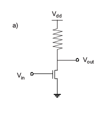
The following excerpt from a book explains the functioning of the circuit below:

When V_in < V_th (device threshold voltage), the supply voltage (V_dd) is measured at the outlet. When V_in is increased above V_th, the NMOS turns on and V_dd is now dropped across the load resistor; V_out is now in common with ground, and the signal at V_out is inverted relative to V_in.

Voltage Inverter Circuit Diagram

Question: Why is V_out = V_dd when the NMOS transistor is off (i.e. when V_in < V_th)? With the transistor off, it seems we should effectively be able to ignore that part of the circuit and compute V_out using Ohm's law to predict the drop of V_dd across the resistor. Why is this not the case?

\$\endgroup\$
5
  • \$\begingroup\$ If the transistor is off, what voltage do you expect to measure at the output if it's not V_dd? Why do you think there will be any voltage drop across the resistor? \$\endgroup\$
    – brhans
    Commented Aug 9, 2018 at 15:57
  • \$\begingroup\$ You would use Ohm's law indeed once you have a load current on the output. But if unloaded V_out is V_dd (in case of ideal transistor of course) as there is no current. \$\endgroup\$
    – Eugene Sh.
    Commented Aug 9, 2018 at 15:58
  • 2
    \$\begingroup\$ The transistor, when off, will have a very large resistance in comparison to the resistor. That's why the voltage drop across the resistor is negligible. \$\endgroup\$ Commented Aug 9, 2018 at 15:59
  • \$\begingroup\$ Thanks for the answers so far guys! I guess part of what I am still not sure of is why the book would be assuming no circuit connected at V_out. This section of the book is talking about integrated circuits (and said this circuit was commonly used in IC's after 1980). It would therefore seem safe to assume that there will always be another circuit attached so that V_out of this circuit is V_in of some other circuit. Do we know that this won't change the circuit behavior "too much"? That is, do we know that this voltage inversion switching will still work if we add another circuit onto V_out? \$\endgroup\$ Commented Aug 9, 2018 at 16:56
  • \$\begingroup\$ It's a normal practice to reason about an "open-circuit" behavior of some circuit component. Here you know both the open-circuit voltage and the output resistance, which are sufficient to analyze larger circuits including it. \$\endgroup\$
    – Eugene Sh.
    Commented Aug 9, 2018 at 17:01

6 Answers 6

2
\$\begingroup\$

From the comments:

... but I am not sure why the book would be assuming no circuit connected at Vout. This section of the book is talking about integrated circuits (and said this circuit was commonly used in IC's after 1980). It would therefore seem safe to assume that there will always be another circuit attached so that Vout of this circuit is Vin of some other circuit. Do we know that this won't change the circuit behavior "too much"? That is, do we know that this voltage inversion switching will still work if we add another circuit onto Vout?

This is actually a fair assumption for MOS if they are driving other MOS devices.

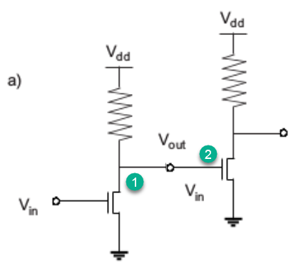
enter image description here

Figure 1. The output (1) of one gate typically drives the inputs (2) of other gates and these have a very high input impedance.

Note that this will really only be true in the steady state condition. When switching occurs then the input gate capacitance has to be charged via the Vdd resistor and a voltage drop will occur as you suspect. It is this switching power dissipation that generates much of the heat in high-speed logic.

\$\endgroup\$
5
\$\begingroup\$

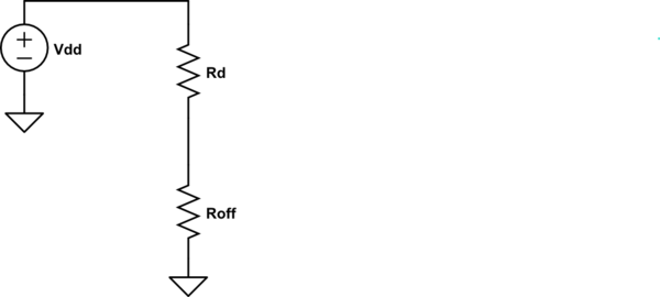
Think of the transistor as having a very large resistance when OFF. So you essentially have this:

schematic

simulate this circuit – Schematic created using CircuitLab

The current is then:

$$ I=\frac{V_{DD}}{R_D+R_{off}}$$

And the voltage across \$R_D\$ is:

$$V=IR_D $$

What happens if \$R_D\$ is very large (say 10M\$\Omega\$)? The current is essentially zero then, and the voltage across the resistor is 0V.

In the ideal case, \$R_{off}\$ is 'infinite' which would mean you'd have an open circuit and no current flows through an open loop. But even for practical values, \$R_{off}\$ forces the current to be negligible.

If there were some other circuitry connected to \$V_o\$ in your schematic, then we'd need to know the equivalent resistance looking into that other circuit because the current may no longer be negligible, but in your case, it is unloaded at \$V_o\$.

\$\endgroup\$
2
  • \$\begingroup\$ Thanks for your answer @sixcab. I follow what you are saying, but I am not sure why the book would be assuming no circuit connected at V_out. This section of the book is talking about integrated circuits (and said this circuit was commonly used in IC's after 1980). It would therefore seem safe to assume that there will always be another circuit attached so that V_out of this circuit is V_in of some other circuit. Do we know that this won't change the circuit behavior "too much"? That is, do we know that this voltage inversion switching will still work if we add another circuit onto V_out? \$\endgroup\$ Commented Aug 9, 2018 at 16:50
  • 1
    \$\begingroup\$ @user334137 Usually the next stage will have a "high" input impedance such that the voltage doesn't drop too much. If the next stage has a high input impedance (compared to Rd), then the effect of the loading is not significant. You are correct, if the loading of the next stage is considerable then there will be a drop in Vo, but chances are the next stage will have a high impedance. \$\endgroup\$
    – Big6
    Commented Aug 9, 2018 at 17:03
0
\$\begingroup\$

You can use Ohm's Law, but you have to recognize that if the transistor is not conducting then no current flows through the resistor. Therefore, there is no voltage across the resistor, which means that the voltage at both ends of the resistor must be the same. Since we know that one end of the resistor is connected to \$V_{DD}\$ then the other end must also have a voltage equal to \$V_{DD}\$. So, when no current flows it must be true that \$V_{OUT}=V_{DD}\$.

\$\endgroup\$
6
  • \$\begingroup\$ Why would current not flow from the V_DD wire to the V_OUT wire? If we removed the V_OUT wire and simply put a voltmeter contact there and another contact on the V_DD wire, then I see the validity of the argument. But if V_OUT is a wire connecting to some other circuit, then how do we know that no current will flow from V_DD wire to V_OUT wire to that other circuit? \$\endgroup\$ Commented Aug 9, 2018 at 16:16
  • 1
    \$\begingroup\$ If it is connecting to some other circuit, then the voltage won't be Vdd. But it is not connected. \$\endgroup\$
    – Eugene Sh.
    Commented Aug 9, 2018 at 16:18
  • \$\begingroup\$ @EugeneSh. The book is talking about this circuit being used as a basic component of integrated circuits, so I would think when used, this circuit would probably indeed have V_OUT connected to some other transistor or circuit to build up logical units. You're saying in this case, the book's quoted statement about V_out = V_dd would be incorrect? \$\endgroup\$ Commented Aug 9, 2018 at 16:45
  • \$\begingroup\$ In case there is a current out (into) the "Out" wire, there will be a voltage drop on the resistor. Without current there is no drop. V=RI, that's it. That is as much as we can say with the information provided. If there are other details in the book - we don't know about these. \$\endgroup\$
    – Eugene Sh.
    Commented Aug 9, 2018 at 16:49
  • \$\begingroup\$ @user334137 You are saying that my answer is wrong because I didn't know about additional information that you failed to provide in the original question. \$\endgroup\$ Commented Aug 9, 2018 at 18:01
0
\$\begingroup\$

Because if nothing is connected to Vout the resistance of air is roughly 10^9Ω, so it forms a resistive divider with the air. Even a 1MΩ resistor will be insignificant compared with that of air the equation for a voltage divider looks like this:

$$\frac{10^9}{10^9+10^6}=0.999$$

In all odds you'll probably have something lower than a 1MΩ resistor there, so you won't even notice the voltage drop. If you measure this with a meter, it will also be high impedance so you'll get a similar result.

\$\endgroup\$
0
\$\begingroup\$

When the NMOS is off the resistance of NMOS is very high and the current is very less between . You can intuitively think as if the the transistor is not present in the circuit and hence you can think of it as an open circuit between the ground and the resistor end.

Hence the circuit becomes something like this.

schematic

simulate this circuit – Schematic created using CircuitLab

As we know there is no current in the resistor, it acts like a normal piece of wire, essentially shorting \$V_{dd}\$ and \$V_{out}\$. This is why you see \$V_{dd}\$ at \$V_{out}\$ when the NMOS is off.

The effective circuit at zero load becomes like this

schematic

simulate this circuit

Note: The above circuits are drawn only for intuitive understanding and in reality a very small amount current flows through the resistor and the NMOS (which may be viewed as a high resistance instead of a open circuit) to the ground.

\$\endgroup\$
0
\$\begingroup\$

Question: Why is V_out = V_dd when the NMOS transistor is off (i.e. when V_in < V_th)? With the transistor off, it seems we should effectively be able to ignore that part of the circuit and compute V_out using Ohm's law to predict the drop of V_dd across the resistor. Why is this not the case?
"It is the case." You are correct.

Except you show no load for a voltage divider to perform KVL, that's all.
When MOSFET is off and may be removed.

\$\endgroup\$

Your Answer

By clicking “Post Your Answer”, you agree to our terms of service and acknowledge you have read our privacy policy.

Not the answer you're looking for? Browse other questions tagged or ask your own question.