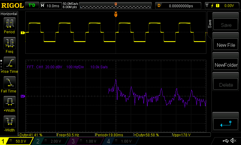
Yesterday I decided to look at the waveform of my portable power inverter. The inverter specs are the following:
- Input: 12 V DC
- Output: 230 V RMS
- Rated power: 300 W
I powered my inverter from a bench power supply at 12 V (powered from a mains power outlet) and set the current limiter to 2 A. The inverter was then loaded with a series of 2 resistors of 1 Mega ohm each (rated at 1.5 W).
At first, I measured the output voltage by connecting the probe of the oscilloscope to the second resistor (therefore measuring half of the inverter output). Then I connected the probe in parallel to the series of resistors.
My oscilloscope is a Rigol DS1054Z. From the datasheet, I read
Maximum Input Voltage (1 MΩ) for analog channel: CAT I 300 Vrms, CAT II 100 Vrms.
According to my understanding of CAT ratings, the system I was probing should be CAT I so the measurement setup is appropriate. Is my reasoning correct? Furthermore, I'd like to understand if I may have damaged the oscilloscope somehow, maybe because of startup/poweroff transients from the inverter.
The probes I used were those shipped with the oscilloscope. I think I was using the x10.
EDIT: I added the waveform of one of the measurements I did

