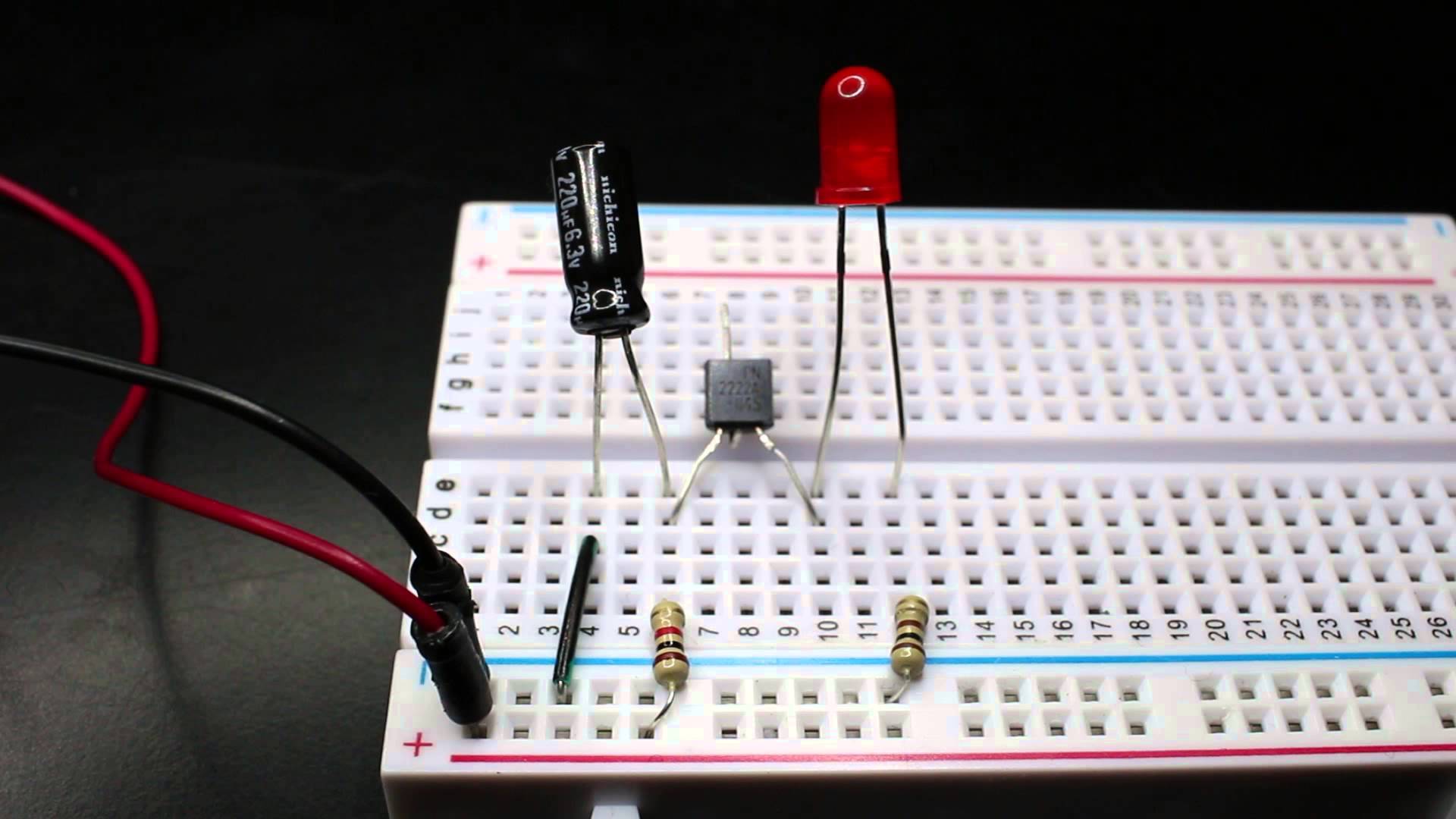
This circuit is a negative resistance transistor oscillator. It's kind of a gimmicky circuit for a beginner, it is a very unusual use of a transistor, and is not actually using the transistor as a switch in the usual way at all. (You can tell that this is the case because the base of the transistor is not connected to anything, which is normally necessary to use it as a switch.)
See this video for some more discussion of what's happening: https://www.youtube.com/watch?v=rpGOKGrcpAk
"Negative resistance" (more properly "negative differential resistance") is a property that some electronic components have, including certain transistors when used in a reverse-biased way. (You can read more about it here: https://en.wikipedia.org/wiki/Negative_resistance#Negative_differential_resistance ) It describes a region of the I-V curve (the curve that describes a device's resistance, or how its current and voltage relate to each other in a circuit) where the current decreases as the voltage increases and vice versa, which is the reverse of the usual relationship for a passive component. I call the circuit 'gimmicky' in part because most of the cheap transistors that do this are not explicitly designed or specified to behave this way -- they happen to do it, but it's not guaranteed to work and might vary with things like temperature, or what batch your transistor happens to be from.
The capacitor does charge and discharge in a loop along with the flashing of the LED. The capacitor can't do that by itself -- the unusual property of the transistor is what triggers it to start and stop charging.
I would not recommend this circuit as an example to learn from, when learning about the use of transistors in basic electronics! It's a very cute gimmick but that's really all it is.


keep its charge the whole time\$\endgroup\$