0
\$\begingroup\$

I've an ESP32-based dev board (LoLin32) which has 26 digital I/O pins. I want to connect 25 common anode RGB LEDs to it. Connecting them in the 'normal' way would require 75 I/O pins, which I don't have ofcourse. I've heard that you could use Charlieplexing to connect n*(n-1) LEDs to n pins, but I don't quite understand how I could use Charlieplexing with common anode RGB LEDs.

Edit: it doesn't neccessarily have to be Charlieplexing, other solutions are welcome too. I know about WS2812-ish things, but that's something I wanted to avoid.

\$\endgroup\$

5 Answers 5

4
\$\begingroup\$

You can't use Charlieplexing with common anode, nor common cathode. You need to have the anodes/cathodes across every pin.

A relatively simple solution in your case would be to acquire a couple of shift registers, the 74HC595 gives you 8 extra outputs at the cost of three pins on the ESP32. You can daisy chain the 74HC595 and have 16 extra outputs and still only paying a total of three pins on the ESP32.

In order to cover 75 LED's, you'd use 75/8 => 10x 74HC595.

If at any one time you will have just one LED activated (which Charlieplexing would force you to do), then you can get away with only one resistor, which would be between the common anode and your voltage supply.

If at any one time you will have several LED's activated (which you can do with 74HC595), then you should place a resistor for every LED. In other words, between every pin on your 74HC595's and their LED's. If you do what I first said, with only one resistor, then the LED's will get darker the more LED's you activate.But with a resistor for every LED, then the brightness will stay the same regardless if you have 1 or 30 LED's activated.


Update

After seeing Transistor's answer I realized that you obviously have 25 RGB LEDs = 4 pins each. It's not some large 5x5 matrix with only one common anode, which I first thought.

This means that you can actually solve this in a much better way than I first proposed.

Here's what I would do if I were you:

  • Connect every red pin of the 25 LEDs together
  • Connect every green pin of the 25 LEDs together
  • Connect every blue pin of the 25 LEDs together
  • Use 4x 74HC595 instead of 10, you will get 32 pins
  • Connect a 220 Ω resistor on 25 of the 32 outputs of the 4x 74HC595
  • Connect the anodes of the 25 LEDs to those resistors
  • Connect the red & green & blue to some remaining pins on the last 74HC595

This will again only take 3 pins on your ESP32, but only 4x 74HC595 instead of 10. And 25 resistors instead of 1 resistor, or 75, depending on how you'd do it.

A very important thing to note, as Transistor has mentioned, is that different LED's have different forward voltage. This means that 220 Ω will make the red LED too bright and the other two will be weaker because they have higher forward voltage drop. This in turn mean that whatever modulating scheme you will be implementing should give less time to red. And you should not use red or green or blue at the same time. You can only activate one LED (by powering its anode through its resistor) at a time.

\$\endgroup\$
6
  • \$\begingroup\$ OK, so when I daisy chain those 10 74HC595's I'll still use only 3 pins but have 80 outputs if I understood it correctly? \$\endgroup\$
    – wb9688
    Commented Sep 12, 2018 at 20:42
  • 2
    \$\begingroup\$ @wb9688 Yep. If you look in the datasheet that I linked, then on page 4 you will see RCLK, SER and SRCLK. SER is the serial data that is clocked by SRCLK. When you want to move the data in the internal register(s) to the pins then you use RCLK. You could get away with only 2 pins, by shorting SRCLK and RCLK, but by doing so, when you are feeding the data into the shift registers, the pins will output everything. In your case it will look very bad. - SER goes to 1 chip, SRCLK and RCLK goes to all chips. - The SER of the 2nd chip takes the first QH' = daisychaining \$\endgroup\$ Commented Sep 12, 2018 at 20:47
  • \$\begingroup\$ Wouldn't what you said in the update make every LED that's turned on have the same color? \$\endgroup\$
    – wb9688
    Commented Sep 12, 2018 at 22:59
  • \$\begingroup\$ @wb9688 You're right. I fixed my error. - FYI, a 1/25 duty cycle, is far above of what LED's can be driven at and still be highly visible. \$\endgroup\$ Commented Sep 12, 2018 at 23:02
  • 1
    \$\begingroup\$ @wb9688 With my updated A, there will be a limit, the duty cycle is going down. So if you have 1000 LED's, each LED will be able to have 1/1000 = 0.1% maximum duty cycle, which I think is very dim. - With my first solution that says "will stay the same regardless if you have 1 or 30 LED's activated.", then you won't run into that problem and you can have even a million LED's without any issue. The problem in that case would be to send data fast enough through all the shift registers so the LED won't appear to be flickering. This can be solved by placing some shift registers in parallel. \$\endgroup\$ Commented Sep 20, 2018 at 14:30
2
\$\begingroup\$

I disagree with all the other answers saying that you can't do charlieplexing with common anode LEDs.

Having common anode only means that al the three sub-LEDs within the single package need to be connected to the same pin in high mode when on.

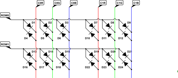
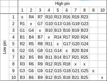
You can think of charlieplexing using a matrix with LEDs in the cells. The column corresponds to the microcontroller pin connected to anode and row to a pin connected to cathode of the LED. Diagonals of the matrix are always unused, since connecting both sides of an LED to a single pin is not very useful. All pins in a single column have their anodes connected together.

If you assign the sub-LEDs of a single RGB LED to a single column, it means that you can drive it using charlieplexing.

For 25 RGB leds you need just 10 pins, with some room to spare. I've made an example matrix that should fit your problem:

RGB led charlieplexing matrix.

\$\endgroup\$
1
  • \$\begingroup\$ It's almost 2 years too late, but maybe this will help someone :) \$\endgroup\$
    – cube
    Commented Jun 14, 2020 at 20:55
1
\$\begingroup\$

enter image description here enter image description here

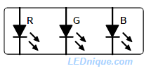
*Figure 1. A 6-pin LED allows access to each LED's individual anode and cathode. Source: LEDs with more than two pins.

No. Charlieplexing would be possible with 6-pin RGB LEDs but not with a common anode or cathode.

schematic

simulate this circuit – Schematic created using CircuitLab

Figure 2. An RGB charlieplexing scheme would need access to individual anodes and cathodes. In this example D1, 2 & 3 are the one RGB LED and D4, 5 & 6 are another.

It would be possible to fabricate a charlieplexable 6-pin, 2 x R, 2 x G, 2 x B back-to-back paired LEDs for this purpose but the market would be small.

Note that another problem with charlieplexing the LEDs would be the differing forward voltages.

\$\endgroup\$
1
\$\begingroup\$

You can't.

Regular multiplexing using n column drivers and m * 3 row drivers (and m * 3 resistors if they're not constant current), where m and n are integers.

So if you pick n = 5 and m = 5 you need 5 + 15 = 20 pins. The duty cycle would be 1/5 = 20%. So for 5mA average current you'll need 25mA row drive and 375mA column drive, which will also be the maximum current for the entire display.

You could also use a shift register (eg. 2x HC595) for the row data, two clocks and one data, so 8 pins, without employing any trickery. You could also use static drive from the HC595s in which case you'd need 5x as many, and 5x as many resistors, but no other components.

Or use the WS2811-style addressable RGB or RGBW LEDs and avoid all of that mess, plus gain PWM brightness control of individual dice without any software overhead.

\$\endgroup\$
0
\$\begingroup\$

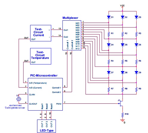
In the following figure, the LED array consists of three common anode LEDs connected together.

The PWM signal created by the controller is amplified by a transistor prior to being applied to the array. The amplitude of 5V is too low to drive the array directly. If the array size is increased, additional paths must be connected to the multiplexer and additional transistors may possibly be required for amplification.

This circuit is from an OSRAM App Note: Driving LEDs with a PIC Microcontroller

enter image description here

\$\endgroup\$
1
  • \$\begingroup\$ The title of that app note would seem to fit. The circuit diagram shows one FET J1 driving all LEDs simultaneously, with the PIC controlling what voltages get multiplexed to "A/D input (current)". All LEDs driven simultaneously does not seem to be what wb9688 wanted to know: The 75 terminals mentioned would allow to control each (part-)LED individually. \$\endgroup\$
    – greybeard
    Commented Feb 2, 2023 at 15:37

Your Answer

By clicking “Post Your Answer”, you agree to our terms of service and acknowledge you have read our privacy policy.

Not the answer you're looking for? Browse other questions tagged or ask your own question.