1
\$\begingroup\$

I am currently working on some improvements on my motorbike, and one of them requires something I have never done before.

I am adding 2 12v LED strips (well, they're built in a piece I am mounting, but that doesn't change anything for the electronics), with the idea that they will normally go on when I power the motorbike and serve as DRL. But I want them to also blink as warning lights when I turn on a switch when I am lane splitting. This of course means that when they blink, the continuous power should be turned off.

So the idea is to make 2 circuits with the same LED strips, one that simply runs the power through it, the other one with a blinking relay in line, and have a relay make the switch from the one to the other. Now I have never worked with a relay before. I think I grasp the concept, there is one circuit (NC) that is closed when the relay is not powered (that would be my DRL circuit) and one circuit (NO) that will close when the relay is powered. As I understand, the COM is basically the power "input" that wil be directed either towards NC or towards NO depending on the state of the relay. The DC+ and DC- seem rather transparent as well although I don't know how things would work inside the relay.

Now the big question: is the IN the key contact that will determine whether the relay is powered or not?

And in my case, is this how I should wire the whole thing?enter image description here

\$\endgroup\$
6
  • \$\begingroup\$ What exactly is the make and model of this relay? \$\endgroup\$
    – Dampmaskin
    Commented Sep 14, 2018 at 14:08
  • \$\begingroup\$ Since you show +, -, and IN terminals on the "relay", I expect that you are using a relay module - a PC board with a relay and driver circuit - rather than a plain relay. A relay will have two "coil" terminals in addition to the contact terminals - the coil terminals are hidden from you by the driver circuit on the board. \$\endgroup\$ Commented Sep 14, 2018 at 15:13
  • \$\begingroup\$ @Max: When you turn left do you want the left DLR to blink in unison with the turn signal and the right DLR to remain on? If so then please edit your question to clarify. \$\endgroup\$
    – Transistor
    Commented Sep 14, 2018 at 17:31
  • \$\begingroup\$ @transistor lane splitting is not turning. He didn't mention turn signals or existing wiring at all. \$\endgroup\$
    – Passerby
    Commented Sep 14, 2018 at 19:21
  • 2
    \$\begingroup\$ @transistor lane splitting in Europe is called riding a motorcycle. Except Germany which only allows lane filtering. Lane splitting is riding between lanes, on the dividing line. A moto going between two cars, who are also moving. Filtering is lane splitting when everyone else is stopped. Totally legal in most countries except for the US and Canada in most areas. Op wants the lights to be more noticeable, by flashing. Basically hazard lights. \$\endgroup\$
    – Passerby
    Commented Sep 14, 2018 at 19:39

2 Answers 2

1
\$\begingroup\$

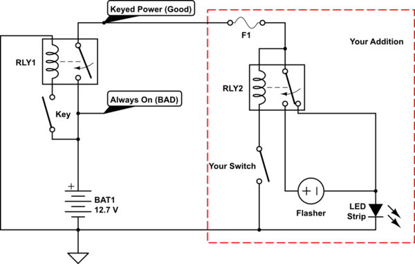
Your circuit is mostly correct. The common would be the 12V keyed voltage source (do not connect it to the battery directly unless you like paying for new ones weekly). The normally closed would be the DRL, and the normally opened the flasher circuit. You'd need one that can deal with the low currents of an LED strip.

The control switch and "in" is where your circuit isn't accurate. Most common relays do not have a separate input from the positive and negative poles of the coil. The switch would be in line with the relay coil power (before or after, does not matter). Plus add an inline Fuse for safety (1 to 2.5 amp would be fine). That's the only change.

schematic

simulate this circuit – Schematic created using CircuitLab

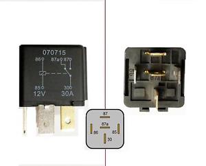
Typical automotive relay:
enter image description here

Alternatively, there are flasher modules that include the relay, so no separate relay is needed.

\$\endgroup\$
-1
\$\begingroup\$

Easy way: use an interval/flashing/timing relay (the name depends on who you ask), which is set up to flash as is. They're how lights flashed on older vehicles.

Harder way: Use a 555 timer circuit.

\$\endgroup\$
0

Your Answer

By clicking “Post Your Answer”, you agree to our terms of service and acknowledge you have read our privacy policy.

Not the answer you're looking for? Browse other questions tagged or ask your own question.