0
\$\begingroup\$

Img fixed

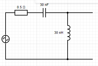
Hello! I have an device which is equivalent circuit is RC as follows in the image I shared: R is supposed to be 0.5Ω and C supposed to be 30nF, but it can vary a little bit between device to device. I cannot touch the leg between the capacitor and the resistor!

While I can measure the capacitor value pretty accurate with LCR meter the resistor reading is off...way off

I tried to find way I could get a hold of the resistor magnitude and it came across my mind that if ill add an inductor in series and If I can work at resonance in the range my signal generator works, 30 MHz, then I could find the value of the resistor or atleast I could know the difference between 0.5Ω to 1Ω. This is the circuit I draw with the values I picked.

Using the signal generator with a steady sine wave, I found out the resonance frequency was more than double that I calculated. I guess it was because of parasitic capacitance and inductance in the BNCs I used.

But what bothered me more was even though I found the resonance frequency the gain was only 5 times greater then the voltage input. Moreover at this point I found out I didn't know how to translate the results to find the resistors value.

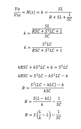
I solved the circuit for steady state as follows:
Imgur

Now the only way this have a chance to be a logic value is if L\K-L >0 . This means that must be k<0. But as I mentioned earlier the gain in scope was of order of 5 ... k=5. I tried to put all that data inside the equations (Fres,S=2*pi*F;L,C) but no matter what I get a negative value for R.

Can you tell me where I am wrong? Because I can't see error in the way I solved the transfer function or in the way I solved the parametric equation.

Also do you guys got any suggestions in how can I measure the resistor? I need a practical idea as I don't have a 30 GHz spectrum analyzer. I got LCR meter, normal scope, and a signal generator which can generate up 30 MHz.

EDIT: Only now I noticed I had a mistake in the capacitor value which is 30nF! I will fix it yet the problem in the equations remains unsolved. Why I am getting a mathematics error and how can it be explained? RLC equations is good , and k is suppose to be greater then 1 in resonance so why from the equation it comes that it can only be solved when k is < 1?

\$\endgroup\$
10
  • \$\begingroup\$ Why not adding another known R instead your proposed L? This would make the equations much easier. \$\endgroup\$ Commented Sep 16, 2018 at 19:32
  • \$\begingroup\$ WHat is your generator impedance? 50 Ohms? Your L is way off 130kHz 30mOhm. What were your RLC results? electronics.stackexchange.com/questions/276538/… \$\endgroup\$
    – D.A.S.
    Commented Sep 16, 2018 at 20:37
  • \$\begingroup\$ Your capacitor has parasitic series resistance as well as inductance (and if you want to be thorough, it's a lot more complicated) and any inductor you apply will also have series resistance as well as capacitance (again, being thorough can complicate it further.) Finally, your generator as well as your measuring instrumentation, cabling, and so on will have their own effects. All of these must be accounted. I think you may need to find a conceptual approach that involves more than one measurement (at least two and perhaps several more) to ferret out needed details to get a result. \$\endgroup\$
    – jonk
    Commented Sep 16, 2018 at 20:40
  • \$\begingroup\$ e.g 0.5Ω±0.4. 3. I am not sure I quite understood the transistor solution . could you explain more on that topic? 4. The capacitor varys also but the RLC meter can measure the capacitor value with satisfying precision. \$\endgroup\$ Commented Sep 16, 2018 at 21:35
  • \$\begingroup\$ Me and maybe some others too want to know what is the actual circuit. We have only your equivalent diagram. \$\endgroup\$
    – user136077
    Commented Sep 16, 2018 at 23:04

1 Answer 1

1
\$\begingroup\$

A total rewrite is done due the edit in the question and the comments.

The circuit has resonant frequency about 5,3MHz. 30nH is so small inductance that all wires and and other parts can well have as much inductance, so the resonant frequency can be totally different, probably lower. If it's higher, you have some unwanted loading. You must have proper low capacitance high Z measuring probes.

Not asked: Inductance 30nH is practical in bandpass filtering resonant circuits at 100...500MHz. At lower frequencies narrow band filtering effects do not happen due high series loss resistances when compared to the reactance.

If you find the resonant frequency, you can measure the impedance of the circuit by adding a shunt resistor for current measurement. Then simply subtract the shunt resistor and you have the total internal resistance of the circuit, also that which is distributed as a non-ideality in the other parts than the assumed 0,5 Ohm resistor.

Comments suggest omitting L out of the measurements, because the left end of R and the right end of C are available. You obviously want to apply ESR measuring techniques to it.

The idea is acceptable, because then L=30nH is out of the problem.

ESR can be measured by measuring the impedance at so high frequency that the reactance of the cap do not hide the result. You can for ex. make a bridge and find external RC series circuit which has the same R and C or at least the same RC product. The frequency must be megahertzes to push the reactance down. That makes the circuit difficult - you cannot have long wires, only centimeters. Avoiding leakage needs care.

You can also construct a pulse integrator, where the capacitor is the RC part of your circuit. The initial jump of the output voltage shows ESR. Unfortunately You will need pulses which rise in few nanoseconds to be able to see anything substantial. Pro level pulse circuit design is a must. If there's substantial stray inductance, it will be seen as ringing which can totally hide the wanted result.

NOTE: helix-type metal film resistors can have too much inductance.

\$\endgroup\$
1
  • \$\begingroup\$ You are right. Only know I see I made a mistake as the capacitor value is 30nF!. I will fix it , yet no one told me what is the problem in the equations? \$\endgroup\$ Commented Sep 17, 2018 at 16:03

Your Answer

By clicking “Post Your Answer”, you agree to our terms of service and acknowledge you have read our privacy policy.

Not the answer you're looking for? Browse other questions tagged or ask your own question.