0
\$\begingroup\$

Sorry if the question is stupid, but my head is still hard as a coconut and I am learning...

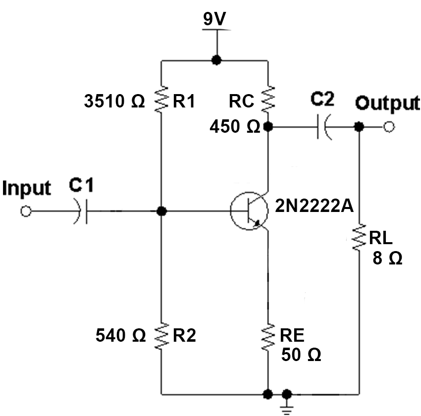
I am dealing with this circuit that I have calculated from scratch.

enter image description here

This circuit was designed to have

  • Vc = 4.5V
  • Ve = 0.5 V
  • Ic = 10 mA
  • Ib = 44.44 uA

Now I am trying to calculate C1 and C2.

The documentation about this is vague and conflicting but as far as I have researched you calculate these capacitors like this:

C1


Several authors say to calculate this capacitor equal to the input impedance at the cut frequency.

Some authors say the frequency must be the lowest frequency, below which, I want to remove from the signal. Some say it must be the highest frequency the amplifier must amplify. I am considering the first hypothesis.

The input impedance of this circuit, I found to be

\$ Z_{IN} = R_1 \ // \ R_2 // \ (r_{\pi} + R_E) \$

where

\$ r_{\pi} = \frac{kT}{qi_B} = \frac{26 mV}{i_B} \$

So, for iB = 44.44 uA, we have

\$ r_{\pi} = \frac{26 mV}{44.44 uA} \approx 581.6746\$ Ω

So,

\$ \frac{1}{Z_{IN}} = \frac{1}{R_1} + \frac{1}{R_2} + \frac{1}{r_{\pi} + R_E} \$

\$ Z_{IN} = 268.82 \$ Ω

If C1's reactance must be equal to ZIN at the cut frequency, lets say 80Hz, then

\$ C_1 = \frac{1}{2 \pi f Z_{IN}} \$

\$ C_1 = 7.4 \mu F \$

C2

For C2 we have the same calculation but now C2's reactance must be equal to the load impedance (8 Ω) for speakers.

then,

\$ C_2 = \frac{1}{2 \pi f Z_{LOAD}} \$

\$ C_2 = \frac{1}{2 \pi (80) (8)} \$

\$ C_2 = 248 \mu F \$

Is this the correct way to calculate these capacitors?

\$\endgroup\$
11
  • 1
    \$\begingroup\$ Is it a 9 volt supply or 4.5 volt supply? Some correction is necessary. \$\endgroup\$
    – Andy aka
    Commented Sep 21, 2018 at 17:35
  • 2
    \$\begingroup\$ As yourself one simple question - what resistance is seen by the capacitor. C1 sees Rin and Rsign in series. C2, on the other hand, sees Rc and RL in a series. And are you really want to drive 8R load via CE amplifier? Are you mad? Notice that your BJT in this configuration can only "sink" the current. And the "source" current is provided via Rc resistor only. So Vo_+max = (Vcc - Vc) * RL/(Rc + RL) ≈ 0.078V \$\endgroup\$
    – G36
    Commented Sep 21, 2018 at 17:42
  • 3
    \$\begingroup\$ Also \$ R_{IN} = R_1||R_2||(r_{\pi} + ( (β+1)* R_E )\$ \$\endgroup\$
    – G36
    Commented Sep 21, 2018 at 17:48
  • 2
    \$\begingroup\$ Also, keep in mind that now you have effectively two high-pass filters in series, therefore, the effective low cut off frequency will be \$ \frac{1}{\sqrt{ \sqrt{2} -1}} = 1.55\$ larger the you expected \$\endgroup\$
    – G36
    Commented Sep 21, 2018 at 18:01
  • 1
    \$\begingroup\$ Spacedog unless you like computer grade old school caps , go with differential Amp DC coupled. Zin becomes closer to 500 Ohms and C2/C1=Zin/8ohms \$\endgroup\$
    – D.A.S.
    Commented Sep 21, 2018 at 18:54

4 Answers 4

1
\$\begingroup\$

Zin is increased by hFE*Re

So change to \$ Z_{IN} = R_1 \ // \ R_2 // \ (r_{\pi} + h_{FE}*R_E) \$

Since Zout=450 Ohms , it cannot drive any AC coupled load < 450 Ohms. So you need to reduce Zout to about 1% to 5% of Rload =8 or 80mOhms Thus hFE=>450/80m=5626 which you can easily achieve with a Darlington driver then AC couple to 8 Ohms or even 4 Ohms

Then C2/C1=Zin/Zload

So Zin is closer to 500 Ohms and choose 2/3 *f(-3dB) HPF breakpoint to get closer with cascaded effects of -3dB on each.

But as I said in comments, a Diff power Amp DC coupled is better.

\$\endgroup\$
6
  • \$\begingroup\$ If I understood your 5th paragraph that sounds Klingon to me. This is what I have to do... Zin = 450. So I calculate C1 for 2/3 of that, or 300R. That, for 80Hz will give me C1 equal to 6.6uF. Regarding the output, suppose I am not using a speaker but rather a 600R impedance headphone. Two thirds of that is 400R. So, \$ C_2 = \frac{1}{2 \pi (80)(400)} = 4.97 \mu F \$... is that correct? \$\endgroup\$
    – Duck
    Commented Sep 21, 2018 at 20:31
  • 1
    \$\begingroup\$ You got it. If two filters have a break at -3dB at some f, then your have to choose each at 2/3f or 2/3R with same result for C so that the two cascaded achieves the f -3dB you want for half power point \$\endgroup\$
    – D.A.S.
    Commented Sep 21, 2018 at 20:35
  • \$\begingroup\$ BRILLIANT, thanks! the only thing I find strange is having the same impedance for input and output. Zout of this amplifier is equal to RC it is 450R, the same value as Zin. Is this normal? \$\endgroup\$
    – Duck
    Commented Sep 21, 2018 at 20:42
  • \$\begingroup\$ No its a useless design but the analysis is what you asked about. An Op Amp would be better. Normally you have emitter followers for current gain and common emitter for voltage gain \$\endgroup\$
    – D.A.S.
    Commented Sep 21, 2018 at 20:43
  • \$\begingroup\$ ok, I know. This is just a design to learn. Thanks \$\endgroup\$
    – Duck
    Commented Sep 21, 2018 at 20:48
1
\$\begingroup\$

enter image description here

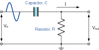
When the impedance of the capacitor equals that of a load resistor, the gain of the circuit is 70.71% i.e. an attenuation of 3 dB. For the load resistor this means: -

  • Bias resistors connected to power rails are to be regarded as being in parallel
  • Base current equivalent resistance is in parallel to bias resistors

If you go lower in frequency, the attenuation is more and if you go higher in frequency then gain approaches unity. So, set a cut-off frequency where an attenuation of 3 dB is of no-consequence to the performance you wish to obtain.

Several authors say to calculate this capacitor equal to the input impedance at the cut frequency.

That depends on what you are trying to achieve but I would play safe and set it at a frequency where my lowest desired signal frequency will hardly be attenuated and, in many cases, 3 dB attenuation might be regarded as too much.

Some authors say the frequency must be the lowest frequency, below which, I want to remove from the signal. Some say it must be the highest frequency the amplifier must amplify.

That would be true of a low-pass filter. The filter in your question is a high pass filter.

\$\endgroup\$
1
\$\begingroup\$

Your calculations are not that bad. Both of your capacitors form a High-pass filter. So, they decide about the lowest frequency you amplifier can amplify.

And we can find the pole frequency (corner frequency) for each capacitor separately.

All we need is to ask our-self one simple question: What resistance is seen by the capacitor?

The \$C_1\$ capacitor sees \$R_{IN}\$ and \$R_{sign}\$ (signal source resistance) in series.

And \$C_2\$ capacitor, on the other hand, sees Rc and RL in a series.

Therefore

$$F_1 = \frac{1}{2\pi C_1 \left(R_1||R_2||\right(r_{\pi} + (\beta+1)R_E))}$$ I omitted Rsig

$$F_2 = \frac{1}{2\pi C_2 (R_C+R_L)}$$

Of course, you can not forget that at this corner frequency the voltage gain of the circuit is 3dB below the maximum gain (\$A_{Vmax} \approx \frac{R_C||R_L}{R_E + r_e}\$).

And because now you have effectively two high-pass filters connected in series at this corner frequency you circuit gain is 6dB below the maximum.

And 3dB corner frequency will be around \$1.55 \cdot F_C \approx 1.55 \cdot 80\textrm{Hz} \approx 124 \textrm{Hz}\$

So, when you are picking the lowest frequency you would like to amplify in your circuit. so, you will need to choose some "Safety margin" when selecting the corner frequency. Also, do not forget that the electrolytic capacitor used very often in this type of a filter will have a very large tolerance +/- 20%, and will lose much of his initial capacitance when aging (30% loss in capacitance or more), but the bigger the cap the bigger the capacitor cost.

All I want to say here is that - one proper solution doesn't exist here, Designing as always is a trade-off between several (often conflicting) requirements.

\$\endgroup\$
0
\$\begingroup\$

Why talk about the capacitor values when the transistor is biased wrong so it is turned off (it would rectify an audio signal) and if it was biased correctly then its output power would be so low that the 8 ohm speaker will barely be heard.

\$\endgroup\$

Your Answer

By clicking “Post Your Answer”, you agree to our terms of service and acknowledge you have read our privacy policy.

Not the answer you're looking for? Browse other questions tagged or ask your own question.