2
\$\begingroup\$

I have a very basic though unsolvable issue so far, I bought a (shitty) mini solar panel, outputting up to 6V and 1W (166mA), and I cant get it to work with the equipment I have or even measure any current.

I do have up to 6V on my multimeter, but I don't see any current output (I plugged the multimeter correctly), is that normal ? Should I use a resistor ? If yes, which resistance would be appropriate ? Could my panel be broken even though it has a potential ?

That is the first part of my issue, which may be silly and due to a ridiculous mistake that I don't see yet, but I have more concerning issue. I bought a (shitty) 3-6V DC motor, that I tested and that draws up to 110mA at 6V at max speed, and starts around 3V drawing 50mA. The motor should run at least slowly with a decent insolation of the panel, but there again, nothing.

Be kind to a person whose strong point is clearly not electrical engineering !

Thanks for you answers.

\$\endgroup\$
9
  • \$\begingroup\$ How much light is on the panel? Full daylight or just indoor light? Put the meter on amps and measure the short-circuit current of the panel - this will give you an indication on roughly how much current it can supply. \$\endgroup\$ Commented Sep 26, 2018 at 13:14
  • \$\begingroup\$ Your first issue is that you've got a PV panel, which has 6V written on it. The 6V will only be there when there is no load (so no current) and under ideal lighting situations. Where did you get "1W" from? I am surprised you can find a mini solar panel with that much power, but that would only be provided under ideal lighting and at peak power (balancing voltage and current). As for why the motor won't turn, it will need a lot (as in twice the steady state) current to start it from a stand still. So you've over estimated your solar panel power and under estimated your required power. \$\endgroup\$
    – Puffafish
    Commented Sep 26, 2018 at 13:16
  • \$\begingroup\$ @SomeoneSomewhere Full daylight on a sunny day, and I did short-circuited the panel with the multimeter, I dont anything but 0. The multimeter has no broken fuse or something, I tried it with a different power source and it displayed the intensity. \$\endgroup\$
    – Adrian
    Commented Sep 26, 2018 at 13:17
  • \$\begingroup\$ @Puffafish The 1W is from the 'datasheet' of the panel. I didnt think about the initial current required to start the engine, that may be an issue indeed. Nonetheless, how can I measure the intensity output of my solar panel ? \$\endgroup\$
    – Adrian
    Commented Sep 26, 2018 at 13:19
  • \$\begingroup\$ You may have a measurement issue if you're getting 0 current. Make sure it's not over-range (often "0.L"), the leads are in the right sockets, and the fuse in the meter is intact. Alternatively, your panel could be stuffed. \$\endgroup\$ Commented Sep 26, 2018 at 13:24

2 Answers 2

1
\$\begingroup\$

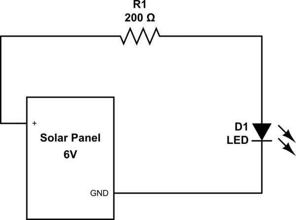
How about trying something a bit different to make things easier. First, let's see if you can light up an LED with using the solar panel.

Build the following circuit.

schematic

simulate this circuit – Schematic created using CircuitLab

Calculating Resistor Value

I calculated the resistor with the following formulas.

6V - 2V (approx drop for LED) = 4V

We have approx 4V to use to calculate the current. Current for the resistor can be about 20mA

4V / .020 = 200 (Ohms)

Does the LED light up?

If the LED doesn't light up then we are misunderstanding how the solar panel is providing current. And I think that is part of the problem. This may help you get to your answer.

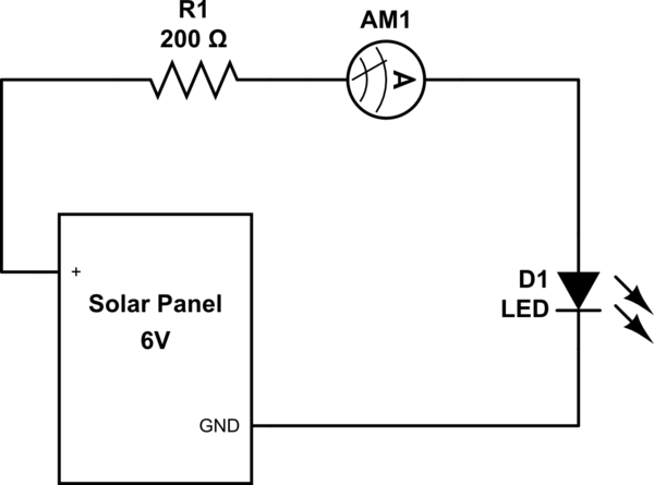
Next thing you can do is insert your ammeter and see what current you may be getting.

Alter the previous circuit by adding the ammeter (multimeter in amp reading mode) inline:

schematic

simulate this circuit

\$\endgroup\$
5
  • \$\begingroup\$ Thanks, I will try this and come back to you. Alternatively, can I put just the resistor and still measure the current ? What if I put a quite higher resistance, like 1K ? \$\endgroup\$
    – Adrian
    Commented Sep 26, 2018 at 13:42
  • \$\begingroup\$ Yes, you can try without LED. Use Ohm's law -- E = I*R (Voltage = Current * Resistance) -- to calculate. 6V / 1000K = 6mA (.006A) You can even use the 6V/200 Ohms = 30mA (.03A). \$\endgroup\$
    – raddevus
    Commented Sep 26, 2018 at 13:44
  • \$\begingroup\$ Thanks, and what if I use a lower 20Ohms resistance,since 6/20Ohms = 300mA, which exceeds the (hypothetical) max current of 166mA of the panel ? \$\endgroup\$
    – Adrian
    Commented Sep 26, 2018 at 13:47
  • \$\begingroup\$ Oh with that last question you got me thinking. It must be that the solar panel has it's own internal resistance. So if you created a circuit with just the panel and a wire going directly from + to GND I believe the panel has it's own resistance so only gives 166mA. That means 6V/.166 = panel's internal resistance is : 36 Ohms. That means if you wanted to light the LED you would want to lower the resistor value to around 150-170 (instead of 200 ohms). \$\endgroup\$
    – raddevus
    Commented Sep 26, 2018 at 13:51
  • 1
    \$\begingroup\$ Noted ! Glad I made you think ;) \$\endgroup\$
    – Adrian
    Commented Sep 26, 2018 at 14:11
1
\$\begingroup\$

A defective solar panel may well deliver its rated voltage with almost no current. This is what would happen if one of the cells is cracked, creating very high internal resistance.

Running a motor from a solar panel works best if you attach a capacitor in parallel, which will provide a high current pulse required to kick the motor out of stalled state.

For the record, I have a small toy motor running from a much smaller solar panel (6x3 cm). It does require a capacitor to start.

\$\endgroup\$
3
  • \$\begingroup\$ Very interesting. When you say "capacitor in parallel" do you mean, for example, across the positive to GND terminals? (One leg connected to + side and one leg connected to GND side?) Also, how do you calculate the size the cap should be? Thanks. \$\endgroup\$
    – raddevus
    Commented Sep 26, 2018 at 18:37
  • \$\begingroup\$ I've been thinking about capacitors for the kick in current, and I am also curious about how to chose the cap value ! \$\endgroup\$
    – Adrian
    Commented Sep 26, 2018 at 19:29
  • \$\begingroup\$ @raddevus I'm pretty sure there's only one way to connect two 2-terminal devices (solar panel and cap) in parallel. Calculating the value would require to specify electrical parameters of the motor as well as the load it's driving (including friction). I just did this via trial and error and found that the motor I have needs at least 1000uF. \$\endgroup\$ Commented Sep 27, 2018 at 7:12

Your Answer

By clicking “Post Your Answer”, you agree to our terms of service and acknowledge you have read our privacy policy.

Not the answer you're looking for? Browse other questions tagged or ask your own question.