1
\$\begingroup\$

I'm building a microcontroller circuit that feeds its output into a microphone input of an audio recorder. The output is a square wave. (Think old-style 3.5mm Square credit card readers).

What can I use to covert a signal in the range of 0..3V to -1..+1V? I'm looking for something like MAX232, but with lower voltage levels.

I could just use a voltage divider and feed 0..+1V to the audio, but I understand that many audio input circuits use AC coupling and the recorded waveform can have unpredictable DC bias. This is undesirable, since the waveform encodes information in zero-crossings.

The question really is about a circuit that can generate negative voltages without a separate negative supply, but for completeness, I can add a few more details. The application is a kind of old-style telemetry format. The data rate is fairly low (~2,000 zero-crossings/second, or 2kbps). The client audio circuit is usually (though not always) a digital recorder. The client records my input and (usually) saves it as a digital sound file. Clients' expectations are that third-party programs can extract original digital information from these files. Sometimes, instead of recording my signal directly, the client feeds my signal into an audio-frequency radio TX (think walkie-talkie) and records the signal from the RX.

\$\endgroup\$
7
  • 1
    \$\begingroup\$ Can you edit your question to give a bit more context. For example, are you hoping to reconstitute the original signal by playing back from the audio recording? Also "since the waveform encodes information in zero-crossings" is unclear. What does this mean? \$\endgroup\$
    – Transistor
    Commented Oct 8, 2018 at 19:44
  • \$\begingroup\$ I hop my edit clarifies the requirements some. \$\endgroup\$
    – iter
    Commented Oct 8, 2018 at 19:50
  • \$\begingroup\$ This seems rather a retro way of doing things (since your original and hope-to-be stored signals are both digital) and reminds me of old telephone modems. The simplest modems worked by transmitting binary zeros and ones using two different audio tones. How much data is to be transmitted in each recording and at what speed? 300 bits per second or 115k? Again, pop all the info into your question rather than in the comments. \$\endgroup\$
    – Transistor
    Commented Oct 8, 2018 at 19:56
  • \$\begingroup\$ It IS very retro, but this technology is making an unexpected comeback. They used to transmit this signal over audio-frequency FM radios. \$\endgroup\$
    – iter
    Commented Oct 8, 2018 at 20:01
  • \$\begingroup\$ I think what I'm looking for is a kind of MAX232 device, but with lower voltages. \$\endgroup\$
    – iter
    Commented Oct 8, 2018 at 20:20

2 Answers 2

5
\$\begingroup\$

I could just use a voltage divider and feed 0..+1V to the audio, but I understand that many audio input circuits use AC coupling and the recorded waveform can have unpredictable DC bias. This is undesirable, since the waveform encodes information in zero-cr ossings.

From the comments:

If it helps, the waveform is similar to Manchester coding.

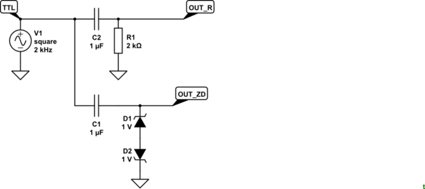
That's a fairly important detail. For one thing it means that the average DC value will be 1.5 V from the micro and that on your audio side the mean DC level will be zero. (This wouldn't be the case in the bitstream example I gave in the comments.) This in turn means that if you could give an adequate lead-in of a string of 1s or 0s that a simple decoupling capacitor would work because any initial DC offset would fade away after a few cycles.

I have never attempted anything like this but something along the following lines might work.

schematic

simulate this circuit – Schematic created using CircuitLab

Figure 1. On the first positive or negative pulse the output will be clamped at about +/- 1.5 to 1.7 V. Thereafter it should swing fairly symmetrically around 0 V.

The C1 value is the default in CircuitLab. I didn't do any calculations.

enter image description here

Figure 2. Simulation of C-R coupling and Zener clamping.

TTL

  • The TTL signal could be dormant low or dormant high. The simulation starts (1) with a high.

OUT_R

  • The right side of C2 starts at 0 V (2).
  • On the first negative-going edge of the TTL signal OUT_R is 'kicked' to -3 V (3). This may overload your audio circuit.
  • As time progresses R1 removes the initial DC bias and, with the values chosen, the signal is centred around 0 V by time (4).

OUT_ZD

  • This also starts of at 0 V (5) due to the capacitor.
  • As in the OUT_R circuit the first negative-going edge of the TTL signal tries to drive the right side of C1 to -3 V. This time, however, D2 will breakdown in reverse mode and D1 will be forward biased. The combination of the 1 V Zener breakdown of D2 and the 0.7 V or so forward voltage of D1 will clamp OUT_ZD to about -1.5 to -1.7 V as shown at (6). At this stage their work is almost done.
  • Subsequent changes of polarity will change OUT_ZD by 3 V from a starting point of 1.5 V away from 0 V so the diodes will hardly have to do any further work (7).

The back to back Zeners just means that the pair work symmetrically on positive or negative pulses. Because Zener's work as a regular diode in forward mode we need to reduce the Zener voltage by the forward voltage drop. You're looking for ±1.5 V and Vf is about 0.6 to 0.7 V so I went for 1 V Zeners.

\$\endgroup\$
4
  • \$\begingroup\$ Thank you for the schematic. I'm not familiar with this use of two diodes back to back--they look like zeners. Is it just a more precise way of dropping the voltage than a voltage divider, or do they serve an additional function? \$\endgroup\$
    – iter
    Commented Oct 12, 2018 at 3:10
  • 1
    \$\begingroup\$ See if Figure 2, etc., helps. \$\endgroup\$
    – Transistor
    Commented Oct 12, 2018 at 6:18
  • \$\begingroup\$ Thank you again. I'm looking on DigiKey, and Zeners have two voltages--Voltage - Zener (Nom) and Voltage - Forward . Which of these is the 1V you're referring to? \$\endgroup\$
    – iter
    Commented Oct 21, 2018 at 4:15
  • 1
    \$\begingroup\$ Digi-Key have a good article on their Maker.io page. Have a read and ping me again if you have any further queries. The "Double Zener Diode Clipping" example is very close to my proposed solution. \$\endgroup\$
    – Transistor
    Commented Oct 21, 2018 at 11:52
1
\$\begingroup\$

I'd say that you don't need a level shifter if what you'll receive in the end is a digital audio file. Whatever biases present in that can easily be fixed with a simple equalizer (FFT filter). Microphone inputs don't usually care if the signal is not symmetrical around 0 (speakers and power amps are a different story).

I know this, because I've done something similar. I have a small transducer that converts light into sound, it's really a photodiode + preamp + a resistor divider so that I get a 0..1V signal, just as you suggested. If my input signal is 50% square wave (e.g. I'm probing the backlight PWM pattern on an LCD screen), the audio file will have a proper square wave, symmetric around 0, because the microphone input's decoupling capacitor acts to remove the "always positive" signal bias. The only gripe is that it can be sometimes slow to do so, as its time constant is typically 0.1-1s, so if you start with a steady state (0V) and then have a digital signal (0-1V), it will begin as a positive waveform, that will slowly sink to the symmetric, with the time constant set by the decoupling cap. If you need a faster reaction to such changes, you can postprocess the audio file with some editing software (e.g. using Audacity - use the Equalization effect and select it to reject all frequencies below your some suitable threshold, e.g. 400 Hz).

\$\endgroup\$
2
  • \$\begingroup\$ Thank you, anrieff. I can remove the DC bias in my own software, but I have no control over the software the clients use. I don't know how well third-party packages in this space deal with DC offset at the start of the recording. It may be worth investigating, but ideally, I'd simply produce a clean signal in the first place. \$\endgroup\$
    – iter
    Commented Oct 8, 2018 at 20:52
  • 1
    \$\begingroup\$ True then, my idea wouldn't work in this case. I'm not really sure, but I think you won't get by without having a negative rail (think TC7660 + negative LDO, to get the -1V rail). The +1V rail is easy. The level shifting part is easy too, as you don't need analogue level shifting, just two levels (so something akin to a CMOS inverter placed on the ±1V rails would work). There might be an IC that does all this, I don't recall any, but you might want to look around first. \$\endgroup\$
    – anrieff
    Commented Oct 10, 2018 at 11:42

Your Answer

By clicking “Post Your Answer”, you agree to our terms of service and acknowledge you have read our privacy policy.

Not the answer you're looking for? Browse other questions tagged or ask your own question.