1
\$\begingroup\$

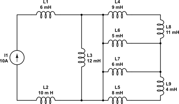
Here's my circuit:

schematic

simulate this circuit – Schematic created using CircuitLab

After doing some series and parallel inductor combining I get the value $$L_{eq}=20.8 mH$$ My question is, how would you go about getting the energy stored in any one of the inductors, given the information in this post (no initial conditions or functions of t for the source current)

Here are some fundamental equations: $$W_L(t)={1\over2}Li^2_L(t)\;\;\;\;\;\;\;V_L(t)=L{{di_L(t)\over dt}}\;\;\;\;\;\;I_L(t)={1\over L}{\int^t_{t_0}V_L(t)dt+I_L(t_0)}$$

If I try to find the voltage using my equivalent inductance, then I will get zero since the derivative of a constant is zero, thus my energy anywhere will be zero.

I'm just curious to see if this is possible, thanks!

\$\endgroup\$
8
  • \$\begingroup\$ The problem is undefined as presented. With zero-resistance inductors, if one of them had a non-zero current initially, the total energy stored would be greater than zero. However, the total energy that you could get out of the thing would just be the traditional inductor energy equation using current and L_eq. \$\endgroup\$
    – TimWescott
    Commented Oct 26, 2018 at 0:11
  • \$\begingroup\$ As far as inductors go, the equations I listed are as much as I know about them (and how to combine them). I'm not sure what reactance means here. Maybe saying no resistance was bad, I'm not explicitly saying that the circuit has no resistance, I just don't have any resistors in the circuit. My question could made into an example by asking what the energy stored in the 12mH inductor is. \$\endgroup\$
    – JustHeavy
    Commented Oct 26, 2018 at 0:16
  • \$\begingroup\$ Do you know how inductors behave in DC circuits versus AC circuits? \$\endgroup\$
    – user103380
    Commented Oct 26, 2018 at 0:19
  • \$\begingroup\$ No, I do not. That is what I am starting to think this circuit might apply to. \$\endgroup\$
    – JustHeavy
    Commented Oct 26, 2018 at 0:20
  • 3
    \$\begingroup\$ Are you sure you got the schematic correct? As drawn, only L1 and L2 have any effect---the rest are shorted out. So the equivalent is 16 mH, not 20.8. \$\endgroup\$
    – The Photon
    Commented Oct 26, 2018 at 0:56

2 Answers 2

5
\$\begingroup\$

After doing some series and parallel inductor combining I get the value Leq=20.8mH

You have miscalculated. All the inductors except L1 and L2 are shorted out, so the equivalent inductance is 16 mH.

how would you go about getting the energy stored in any one of the inductors, given the information in this post (no initial conditions or functions of t for the source current)

You can use the well-known formula

$$E = \frac{1}{2}LI^2$$

Since you have an ideal current source, there's no need to worry about the history of how the current reached this state; you know the current through each of the non-shorted inductors is 10 A.

So the energy stored in the 6 mH inductor is 0.3 J, and the energy stored in the 10 mH inductor is 0.5 J.

Now, in the absolute ideal of circuit theory, if these are perfect ideal inductors, it's possible for any amount of current to be circulating through the other (shorted out) inductors without affecting L1, L2, or the current source, and thus any amount of energy might be stored in them. You don't have any information to find out how much this energy is.

But really in circuit theory when we say we have an ideal inductor with "zero" resistance, we actually mean the resistance is too low to significantly affect any time constants or dynamic behavior in our circuit. But we know there is actually a non-zero resistance and so if this circuit is left to run for any appreciable amount of time, the small parasitic resistances of the inductors will absorb any energy in the shorted inductors, and they will have 0 current flowing.

On the other hand if this circuit was obtained by considering what happens when a switch is closed at some time \$t_0\$, you might be expected to use the configuration of the switch prior to the switch closing to determine the current through some of the shorted inductors.
\$\endgroup\$
2
  • \$\begingroup\$ While, "realistically" your answer is correct, please explain how i(L1) = i(L2) = 10, i(L3) = 1000, i(L4) = i(L5) = i(L8) = i(L9) = -990 (all currents DC) is not consistent with KVL and KCL. This would obviously have a great deal of stored energy. \$\endgroup\$ Commented Oct 26, 2018 at 21:23
  • \$\begingroup\$ @WhatRoughBeast, you saw where I said, " if these are perfect ideal inductors, it's possible for any amount of current to be circulating through the other (shorted out) inductors without affecting L1, L2, or the current source, and thus any amount of energy might be stored in them.", right? \$\endgroup\$
    – The Photon
    Commented Oct 26, 2018 at 21:36
5
\$\begingroup\$

OK, so that's a trick question. Or a trick circuit, take your pick.

Let's start at the beginning. At some point the current through the circuit will be zero amps, and then the current source will be activated.

During turn-on, when the current source is connected or otherwise activated, the existence of a non-zero di/dt will produce non-zero voltages in all inductors which actually conduct current. Due to the short circuit across L3, there can be no voltage produced in L3 to L9, and consequently no current introduced into L3 to L9. With no instantaneous current at any time, the integral of the current in L3 to L9 must also be zero. So, at steady-state, only L1 and L2 have current flowing through them, and the current must be identically 10 amps in each.

From this you can calculate the total energy stored in all inductors.

\$\endgroup\$

Your Answer

By clicking “Post Your Answer”, you agree to our terms of service and acknowledge you have read our privacy policy.

Not the answer you're looking for? Browse other questions tagged or ask your own question.