2
\$\begingroup\$

The charging current I’m talking about would be the one between un-shorted phases and ground when there is a short to ground in one of the phases in a distribution network or facility. I'm not talking about the charging current in a transmission network where transmission lines at extremely high voltage accumulate charge between them and may possible increase the voltage (specially if the system is not designed properly).

Please see this web page section “Estimating”. The current they are trying to estimate there is the one that I would like to define and understand. Also see this paper

Every article I have seen about estimating charging current takes for granted that the reader knows what charging current is and how it originates, and doesn't properly define it before explaining how to measure or estimate it.

I have been reading and the best definition I have found so far is :

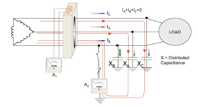
"Each phase of a three-phase system exhibits a certain amount of distributed capacitance to ground, shown here as three capacitors. A capacitive current flows through these (1). If one of the phases shorts to ground causing a ground fault, the charging current for the other two phases will flow through the ground fault (2)."

circuit

Apparently the way to directly measure charging current in small ungrounded systems (in which the charging current value is under 10 A) is to short one of the phases to ground and measure the current. As seen:

how to measure it

What is hard for me to understand intuitively is what I have marked as (1) and (2) on the definition:

(1) There is current flowing(leaking) out the circuit to ground from each of the phases even when there are no faults and the value of this current is several Amps! Mind-blowing!!!

(2) If I short a phase to ground. What I will see is the charging current from the other 2 phases coming from ground to my shorted phase through ammeter A2. And what about the current supplied by the utility and that was normally flowing through the phase I have just shorted? What happened to it?

(3) Will ammeter A1 continue to measure 0 after I short one of the phases? Why?

\$\endgroup\$
3
  • \$\begingroup\$ What have you tried so far to solve this issue on your own? The essence of your question is not clear. Is this about what it takes to establish a safe high-impedance ground for a given 3-phase delta power feed? \$\endgroup\$
    – user105652
    Commented Nov 6, 2018 at 0:30
  • \$\begingroup\$ I'm sorry I was in a hurry yesterday and couldn't elaborate a proper question. I'm not trying to estimate charging current. I'm trying to understand where it comes from and how it is measured \$\endgroup\$
    – VMMF
    Commented Nov 6, 2018 at 13:27
  • \$\begingroup\$ Hadn't heard the term before seeing this, so not sure if this is (a) valid, (b) helpful, but... 1. Imagine a section of the network somewhere in the middle of the line. 2. Instead of a single capacitor between each phase and ground, think of two: one to the left; one to the right. 3. Think of ground as a "virtual" wire alongside the three phases. 4. If you short one phase to the (virtual) ground, then current flows from the other two phases, through the left/right capacitors "into" the section of (virtual) ground under study, and then through the short into the final phase. \$\endgroup\$
    – TripeHound
    Commented Nov 6, 2018 at 15:58

2 Answers 2

0
\$\begingroup\$

"For a more precise estimate, use manufacturer’s data to sum up the different circuit elements that contribute to charging currents, such as cable capacitance per 100 feet, surge arrestors, motors, etc"

Charging current happens in any electrical condition, its the total capacitance of the whole system in question. You see it profoundly in transmission lines due to the insane capacity of long wire lengths. But it basically exists everywhere just to lesser extent. Hope that helped, its basically spec info that you would have to gather based on the install in question. as for the formula that will provide that, that would be another thing.

\$\endgroup\$
1
  • \$\begingroup\$ Thank you very much for your answer! I know that the part that you are quoting is on one of the references I provided. I'm not trying to estimate charging current, I would like to understand it intuitively. Please see my updated question \$\endgroup\$
    – VMMF
    Commented Nov 6, 2018 at 13:29
0
\$\begingroup\$

(1) There is current flowing(leaking) out the circuit to ground from each of the phases even when there are no faults and the value of this current is several Amps! Mind-blowing!!!

This is correct. Since these lines are very long, when one phase is shorted to ground, every bit of the un-shorted ones leaks a few tiny undetectable mA through air to ground. Just as displacement current inside a capacitor. The sum of all these contributions can reach several Amps going to earth, but at no single point several Amps are flowing, so there is no visible arc flash or similar thing.

(2) If I short a phase to ground. What I will see is the charging current from the other 2 phases coming from ground to my shorted phase through ammeter A2. And what about the current supplied by the utility and that was normally flowing through the phase I have just shorted? What happened to it?

The current supplied by the utility, which in this case would be known as short circuit current, in the case of an ungrounded system (the delta system in the image) with a fault to ground, doesn't have a point to return to the transformer, so it can't flow. That is why in ungrounded systems ammeter A2 is only seeing charging current. If the system was grounded (wye) or resistive grounded (wye with Neutral Grounding Resistor = NGR) ammeter A2 would see the vectorial sum of short circuit current (from the point of fault to the neutral of the wye in the transformer) and charging current (from lines through air to ground to the point of fault)

(3) Will ammeter A1 continue to measure 0 after I short one of the phases? Why?
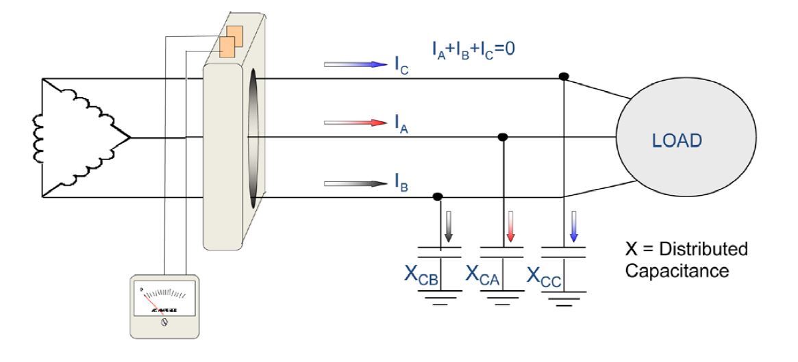
Yes. Ammeter A1 reads the current (short circuit + charging) through the 3 phases. Since all the current that flows to the load, returns from that same way from the current transformer (CT) point of view, A1 is unable to detect any missing current and reads 0 Amps. This can be said because the fault is to the right of the CT so charging current flows compensated before it and no short circuit current ever flowed. This explanation is only valid for this specific scenario in the image. If the system was somehow grounded, short circuit current will flow back to the transformer through ground and since an imbalance would be seen in the CT, A1 would not read 0.

\$\endgroup\$

Your Answer

By clicking “Post Your Answer”, you agree to our terms of service and acknowledge you have read our privacy policy.

Not the answer you're looking for? Browse other questions tagged or ask your own question.