2
\$\begingroup\$

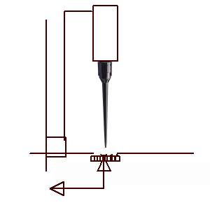
I am building a liquid handler (a CNC machine that pipettes small quantities of liquids). The machine switches polypropylene "tips" between pipetting different fluids. Positional accuracy within 0.5mm of the pipette tips is key. However, I have sourced tips from several different manufactures and in each batch there are some tips that are slightly bent/warped. I would like to find the position of the bottom of the pipette tip to calculate any offset into the g-code if the pipette tip is bent. (Note: The diameter of the bottom of the pipette tip is 0.75mm.) These tips are very fragile, so I would prefer not to bump them into mechanical switches. I wanted to use optical switches, but polypropylene has a high transmission of IR wavelengths, and thus do not trigger optical switches.

So my question: is there a way to optically detect polypropylene? Polypropylene has a low transmission at 3250 nm. This is my first post to StackExchange let me know if detail/formatting is lacking. Thank you for your time.

\$\endgroup\$
2
  • \$\begingroup\$ Does polyprolylene scatter enough light that a polarised light gate can detect the change in brightness? I can't find good sources on that. \$\endgroup\$
    – Jeroen3
    Commented Jan 18, 2019 at 9:00
  • \$\begingroup\$ SMT pick&place machines for PCB assembly have a similar problem. There's a small random offset after the vacuum nozzle picks up an SMT component. In the pick&place machine, this is addressed with the bottom camera. The nozzle hovers each component over a camera and calculates the offset correction. This method of offset correction is fast. Maybe it's a overkill for your application. Maybe your fluid handler can do with a slower and simpler methods which others have already suggested. \$\endgroup\$ Commented Jan 18, 2019 at 22:31

3 Answers 3

3
\$\begingroup\$

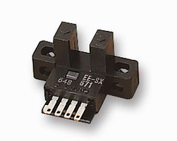
For an industrial application the normal approach would be to submit a sample of your product to an industrial sensor vendor and let them propose a solution. A through-beam slot sensor should be able to give very good resolution. You would program the machine to move the part across the sensor, stop when the beam is broken and then make your move relative to that position.

enter image description here

Figure 1. An opto slot sensor has an infrared LED on one side and photo-transistor on the other.

You might be able to find one with a logic output which would simplify your setup rather than have to amplify the photo-transistor output current.

enter image description here

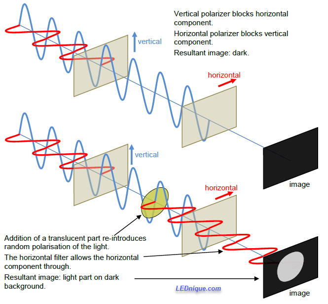
Figure 2. Using polarized light to detect translucent part. Image by LEDnique.

Another approach would be to use a vision system to report the position. Since your part is translucent you could use polarisation of light to your advantage. Illuminate the part from the rear using an LED backlight covered with a polarizing filter. Add a polarizing filter to the camera and rotate to 90° so that the backlight appears black. Now when a part is positioned in between the filters it will randomize the polarization of the light passing through it and the part will show up as a light image on a dark background.

\$\endgroup\$
1
  • \$\begingroup\$ Thank you for your thoughtful answer! I will look at employing a vision system in my build. \$\endgroup\$
    – David F.
    Commented Jan 18, 2019 at 17:28
1
\$\begingroup\$

Droplets of Poly. will diffuse light easily and may be detected dropping past a vertical camera with a diffused back reflector such that the attenuation loss from the reflection coefficient and light spreading is easily detected with 1/60th second captures over a 1cm area or a droplet speed of 60 cm/s. If it is faster, then define it.

It is possible to locate an optical sensor 10mm effective aperture camera array to accept a calibration drop and measure the offset from the optical datum home switch to measure any change from the working position home defined as the xy axis droplet centre position. This can be used to create a new home work position from which a stepper gantry can then locate to the system design accuracy be it full steps of say 0.5mm or 1/16 steps of < 0.05mm accuracy.

The g-codes for doing the correction calibration is easy. The challenge is to choose an optical reflective array sensor like a 9600 dpi laser mouse chip to detect the peak centre of the droplet and convert this into a geometric work 0,0 position which is just near the datum 0,0 optical home positions in a corner or single linear axis. Cleaning the array sensor after calibration might be a manual operation.

Here the SNR of the optical array signals only have to report the error in the geometric xy mean of the optical array. This can confirm as a go-no go or be used in error correction for position error in the servo by some method. TBD

enter image description here

\$\endgroup\$
3
  • \$\begingroup\$ Thank you for taking the time to help with my problem! The tips are replaced frequently, sometimes more than a couple of times a minute. Cleaning the sensor would add a lot of complexity to the build, but I will keep this solution in mind. \$\endgroup\$
    – David F.
    Commented Jan 18, 2019 at 17:31
  • \$\begingroup\$ another approach is to use vertical camera with dropping pipette drops synchronized to capture position error at datum and collect in a waste container. Any resolution is possible with cheap cam chips with adjustable focal length (lens ring thread) and diffused reflected background from light source to detect drops synchronized to trigger. Then error correct by computing new work Home position. Move and send G code. then verify. or move until null error then send g code. I use this github.com/Gerritv/Grbl-Panel/wiki with Arduino + CNC shield and Windows app. \$\endgroup\$
    – D.A.S.
    Commented Jan 18, 2019 at 18:01
  • \$\begingroup\$ THis approach is how Pick N place machines work. Except they just locate Fiducial mark and zero offsets. \$\endgroup\$
    – D.A.S.
    Commented Jan 18, 2019 at 18:05
0
\$\begingroup\$

I doubt that you can easily find LEDs/Photodiodes/photo transistors in the 3250nm band, but you should be able to target the much narrower ~1450nm set of bands.

This LED operates at 1450nm with a bandwidth of 90nm. It might have enough sensitivity around that wavelength peak to detect both of the polypropylene absorption peaks in that region.

You can use the same LED as a photodiode, although these are not specified for that purpose, its absorption spectra will be in the same region and should work well for your application. You might probably have to mask them to achieve the mechanical tolerance you require.

\$\endgroup\$

Your Answer

By clicking “Post Your Answer”, you agree to our terms of service and acknowledge you have read our privacy policy.

Not the answer you're looking for? Browse other questions tagged or ask your own question.