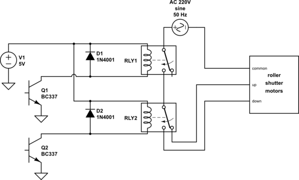
I have a circuit used to control roller shutters in my home, which roughly can be seen in the schematic below.

simulate this circuit – Schematic created using CircuitLab
It works, but after some months, some relays stopped working. The relays are rated 16A 250V~, and they operate at 5V. We suspected some faulty components (although they were bought in a reputable store) and after some extra failures I discovered that light "percussive maintenance" solved the issue, so I suspect that the relay contacts were somewhat slightly fused together, if that makes sense. But it's not a full-blown-fused-contacts scenario, just... slightly enough to not switch anymore until gently tapped.
I realized that I had neglected to add a snubber there. I am more a microcontroller guy myself, so I read a little bit on the internet and decided to add a snubber, specifically: this KEMET one which is a 100n 100R. I was hoping it would make sense in this circuit, and was unsure if it was better to put them across the contacts or across the load and I ended up trying it across both common-up and common-down in the cover contacts.
Still, when stopping the shutter movement from either directions, I have sometimes seen sparkles inside one (RLY1) or both relays.
What should I improve, and what are my options? The PCB is done and is somewhat big for a DIY small hobbist like myself. And it is placed in a hard-to-reach small enclosure. I thought that maybe I didn't properly place the snubbers, but physically it's hard to test them in a lot of different positions. I was considering the option to change the RLY1 for a SSR with zero-cross (hoping the zero-cross would solve itself some of the issues), but still, it would mean to redo and patch some electronics and I fear being mistaken and ending up burning the SSR.
