3
\$\begingroup\$

I have a small board that uses the SC189C buck regulator to take 5 V down to 3.3 V. For whatever reason somewhere between 25% and 50% of these boards have had the voltage regulator fail at some point, including in ways that have killed the microprocessor they are supposed to power (an ATSAMD21E18A).

In some cases, the regulators have failed with an internal short. In other cases, they lose the ability to regulate well, and I have seen the switching frequency at about 40 kHz and also at 5 MHz when it is supposed to be fixed at 2.5 MHz. In that specific case, using my multimeter to probe the voltage on the output voltage sense pin causes the switching frequency to change between the two and the output frequency to change with it. In both cases, the output voltage sense pin is "close" to the 1.2 V it is supposed to be driven to, but off, at 1.18 or 1.25 V, and stable (no apparent ringing) at these values. In another case, they end up giving a total 1.7 V output for a while.

So far, I have simply been replacing a lot of the failed SC189C regulators. This has worked fine, but I am interested to know what might have caused the failures in the first place, and if there is any additional circuitry I can add to protect them. The datasheet seems to imply they are robust with protection features.

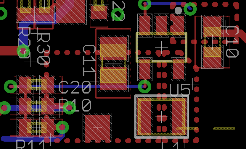
The nominal current draw of the circuit is 130-150 mA, and we are using the SOT23-5 package with the recommended layout from the datasheet: https://www.semtech.com/uploads/documents/sc189.pdf

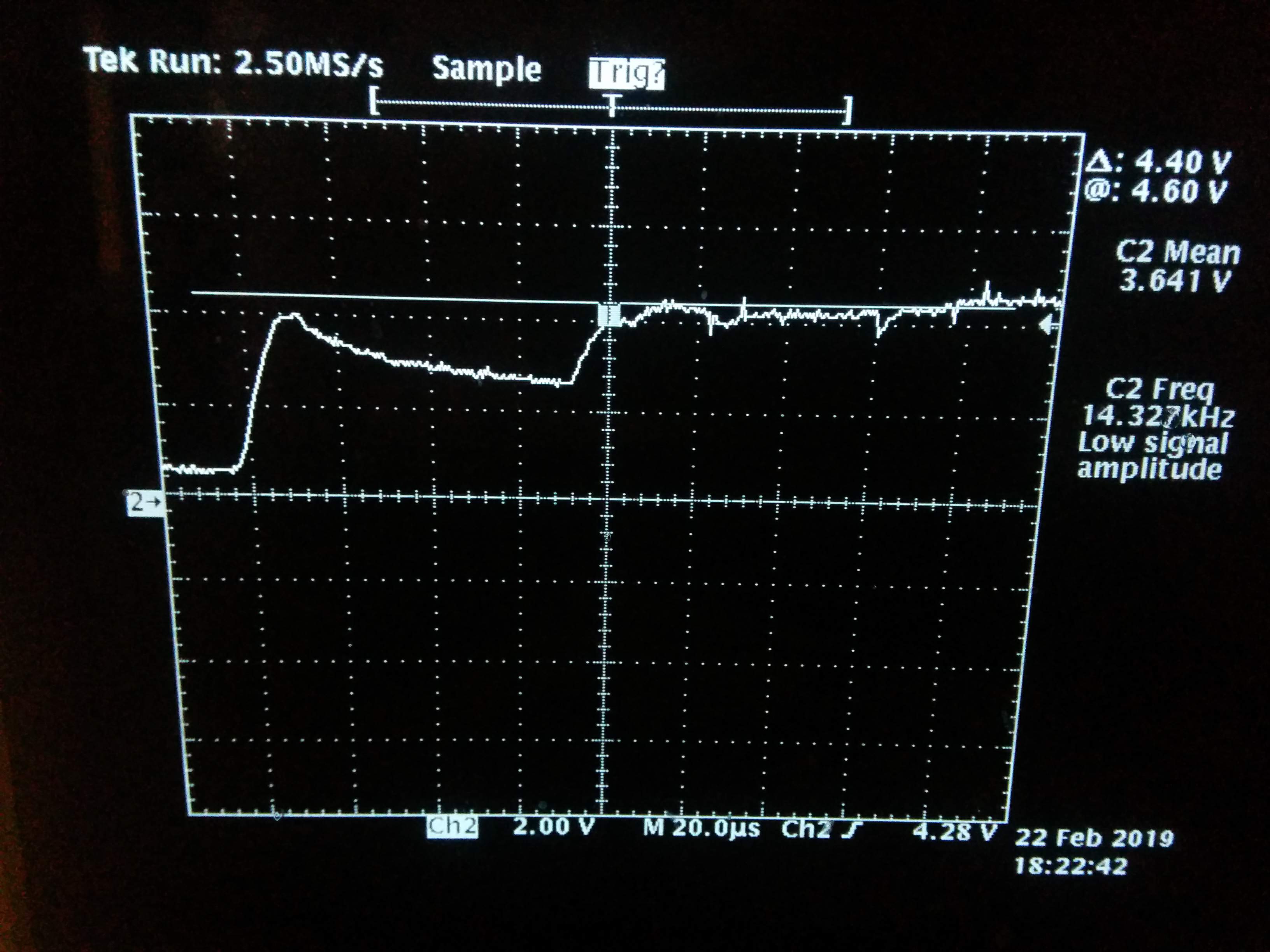
Input capacitance: 10 uF
Inductor: 1 uH, 55 mohm, 1.6 A (LQM2HPN1R0MG0)
Output capacitance: 22 uF, X5R
R_fb1: 17.4K, 1%
R_fb2: 10.0K, 1%
C_ff: 6.8 nF

Schematic Pcb

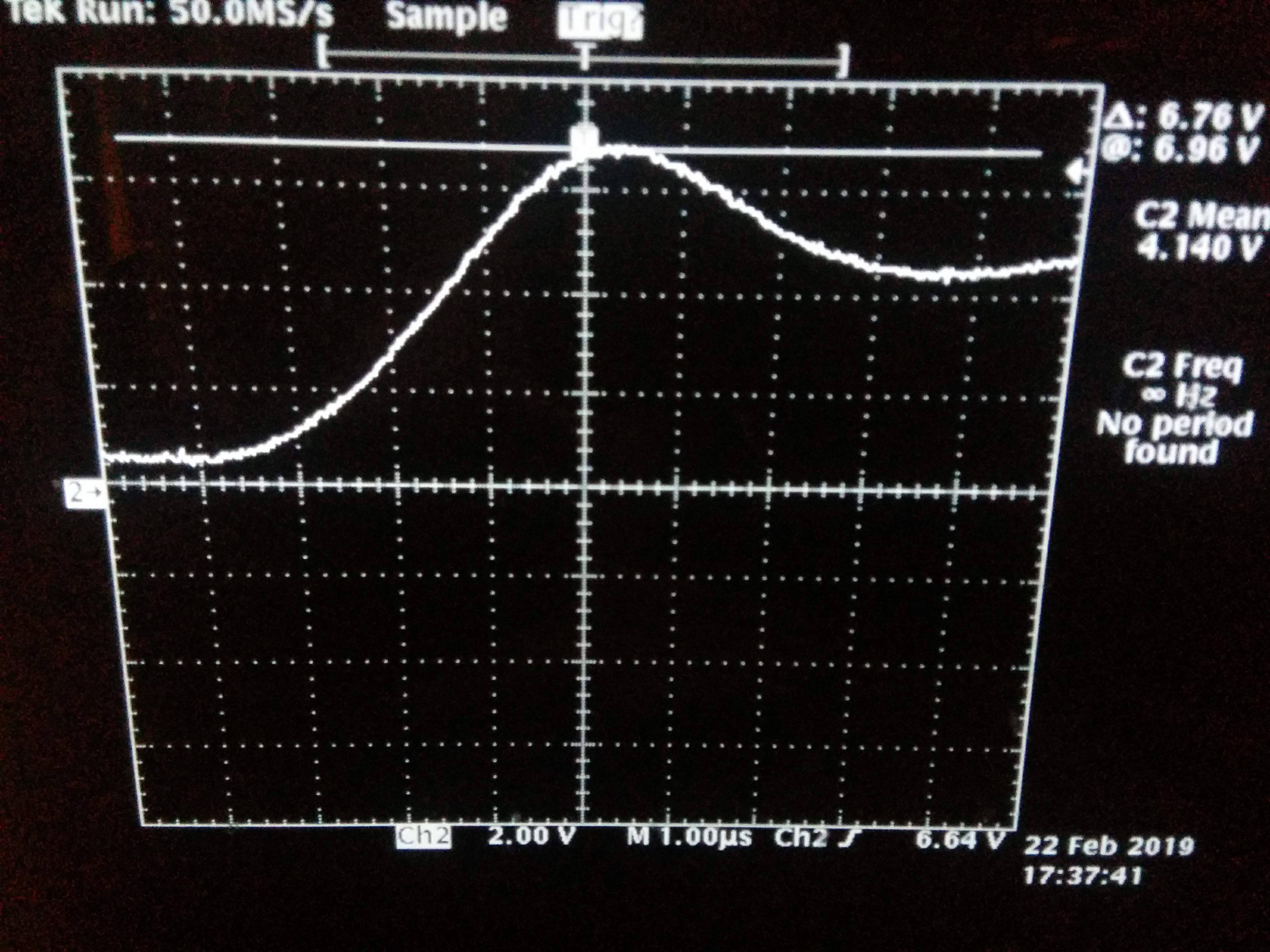
The following is what I see with the probe directly across C10 when I insert the USB cable into a battery. It seems to not do this when I insert the USB cable into other 5V sources. The actual peak voltage there is 6.76V.

InsertionTransient

\$\endgroup\$
2
  • \$\begingroup\$ This is exactly why we discourage broad, open-ended design review or debugging questions here on EE.SE -- the answer(s) tend to become long strings of unrelated edits and/or comments. While this might help you with your immediate problems, it is of no value to the site overall. We DO allow design review questions in which you explain your choices and then focus on a few points about which you still have doubts. To get a better feel of what is or is not acceptable, search for "design review" on the meta site. \$\endgroup\$
    – Dave Tweed
    Commented Feb 22, 2019 at 22:42
  • \$\begingroup\$ Comments are not for extended discussion; this conversation has been moved to chat. Any conclusions reached should be edited back into the question and/or any answers. \$\endgroup\$
    – Dave Tweed
    Commented Feb 22, 2019 at 22:42

1 Answer 1

3
\$\begingroup\$

The main problem was that the input capacitor was ceramic with a low ESR. As it quickly charges up on startup, inductance in the wire and in the USB battery supply 5V source cause the capacitor to overshoot its voltage up to 6.7V+ which can apparently kill the SC189 with repeated exposure to this voltage, as it has an absolute maximum of 6V.

The solution was pointed out by @mkeith, and is addressed extensively in the application note Ceramic Input Capacitors Can Cause Overvoltage Transients

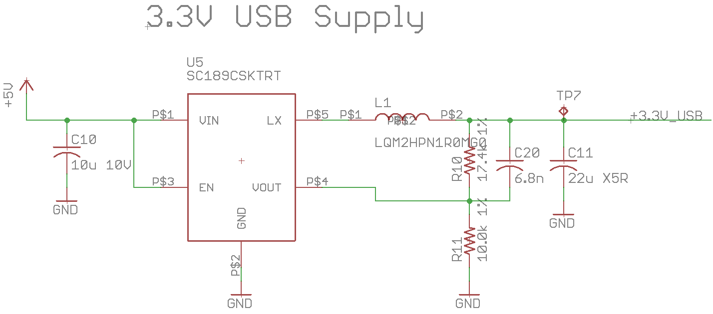
By putting a electrolytic 4.7 uF capacitor in parallel with C10, the two capacitors are not able to charge as fast and the electrolytic apparently starts to absorb the charge that the ceramic capacitor gets on startup, giving us a similar shape as before, but at safe lower voltages. I got the following figure, showing the over-voltage condition has been mitigated. Since there is still the weird non-monotonic start, I should probably use a larger capacitor.

enter image description here

\$\endgroup\$
1
  • \$\begingroup\$ So what's going on in that graph with the double rise? The initial rise is while the high ESL of the electrolytic is preventing electrolytic from absorbing the charge so the ceramics take it all? Then the negative slope is when the current starts flowing through the electrolytic ESL and charging the them so they drag the line down and draw charge from the ceramics? \$\endgroup\$
    – DKNguyen
    Commented Feb 22, 2019 at 23:00

Your Answer

By clicking “Post Your Answer”, you agree to our terms of service and acknowledge you have read our privacy policy.

Not the answer you're looking for? Browse other questions tagged or ask your own question.