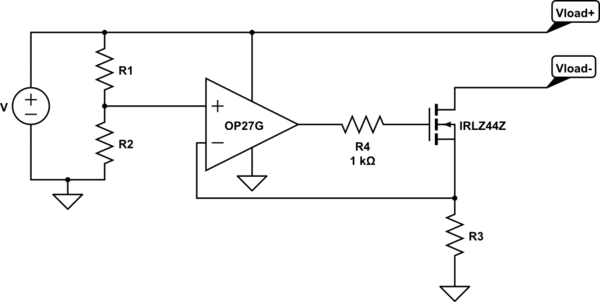
The opamp is in a non-inverting amplifier configuration with a gain of 1. As always, the output of the opamp will do whatever it takes to make the voltages at the + (non-inverting) and - (inverting) inputs identical. Because the forward gain is 1, and the top of R3 is connected to the - input, the opamp will do whatever it takes to make the voltage at the top of R3 equal to the voltage at the + input. As R1 and R2 change, the + input voltage changes, and the opamp makes sure that voltage is at the top of R3.
Now for the fun part. Between the opamp output and R3 is the FET, which is essentially a voltage-controlled resistor. As the output of the opamp goes up and down, the resistance of the FET between its drain and source terminals (called Rds) goes down and up. The higher the gate voltage, the lower the resistance.
If the circuit were simply the load and R3 in series, then if the load resistance changed, the current through the string would change (Ohm's Law). But that FET is in there; its resistance is in series with the load. The load, FET, and R3 form a series string, and the opamp can adjust the FET's resistance. If the load resistance changes, the current through the string changes, the voltage at the top of R3 changes, and the opamp adjusts the FET's resistance to keep the R3 voltage equal to the input voltage. R3 is called the sense (or shunt) resistor. The opamp works to keep the voltage across it constant, and thanks to Ohm's Law that means the current through it (and the rest of the string) is constant. By constant I mean constant as long as the input voltage is constant. Change the input voltage, and the opamp adjusts the FET so the string current is correct for that voltage.
The net result is that the current through the load is not determined by the resistance of the load. Over the range of voltages that the circuit can handle, the current through the load is a constant even when the load resistance changes. The only thing that changes the load current is the + input voltage.

